Seismic Corner – Advantage Steel Issue No. 50
A system developed for seismic resistance
Common lateral-load-resisting systems, such as rigid frames, concentrically braced frames and shear walls, have traditionally served to resist wind effects and provide stability in general. Since the trend towards more rigorous design for seismic loads began several decades ago, these systems have been adopted to resist seismic effects at various levels of ductility, through continuing modifications and improvement. The EBF is the only generic system that was developed specifically to be an effective seismic-force-resisting system.
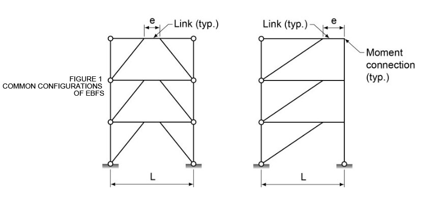
In concentrically braced frames, the braces typically intersect a beam or a beam and a column at a common work point, avoiding connection eccentricity. In contrast, these members in the EBF configurations intersect eccentrically and create an eccentric link at each strategically selected location (see Figure 1). These links, typically quite short, attract large shear forces when subjected to ground motion; long links incur large bending moments also. Research studies conducted since the 1970s have demonstrated that well-proportioned EBFs behave very well. The concept was initially embraced by engineers in the U.S., followed by engineers in Japan, Canada and New Zealand, etc. The first EBF project in Canada was built in the 1980s and EBF design provisions were first introduced in CSA Standard S16.1-89 (as Appendix D). To date, EBFs appear in numerous projects around the world.
 Capacity design
Professor Igor Popov initiated the first research project on EBFs in the 1970s when steel structures were designed in the U.S. using the allowable stress method. His vision guided his team to pursue not only an inelastic design solution but also a design philosophy ahead of their time – capacity design approach. In EBFs, the yielding elements, being the links, are precisely defined and contained while the rest of the system can be proportioned to remain elastic (capacity protected). The system presented itself to be a perfect example for capacity design, a term that did not exist in the steel design textbooks until many years later.
Displacement-based design
As the trend towards displacement-based design gains popularity, research papers and textbooks written for the topic are readily available. When will it find its way into the design codes? It depends on which jurisdiction or nation we practice in and what kind of structures we do. It is generally felt that displacement-based design for multi-storey building structures may be too complex to warrant its use in practice today. However, it is part of the performance-based design provisions proposed for CSA S6-14, Canadian Highway Bridge Design Code.
Displacement limits (for collapse prevention level), in the form of maximum link-end rotations, are already an essential design requirement for EBFs. Since the links are precisely defined and isolated while the rest of the system remains elastic, displacement-based design focuses on the links. The design procedure applies to multi-storey structures as well.
Multi-level performance-based design
As mentioned earlier, performance-based design provisions have been proposed for CSA S6-14. To meet multi-level performance, ‘Other Bridges’ (normal), for example, may have ‘repairable damage’ following a 475-year event, ‘extensive damage’ following a 975-year event and may need to be replaced following a 2475- year event. ‘Lifeline Bridges’ are permitted to suffer ‘no damage’, ‘minimal damage’ and ‘repairable damage’ at the 475-year, 975-year and 2475-year levels respectively and the designer must provide an explicit demonstration of compliance. Obviously, multi-level performance-based design can be significantly more onerous.
The seismic provisions in NBC 2010 focus on one level of structural design objective – collapse prevention at a 2475-year event. Future codes may include serviceability requirements for more frequent events.
Modular EBF link
Do we find an answer in EBFs for multi-level performance-based design?
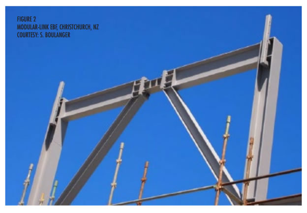
Professor C. Christopoulos and his associates at the University of Toronto, in collaboration with Professor R. Tremblay at Ecole Polytechnique, are the pioneers of modular link research in Canada. In traditional EBFs, the links are part of a beam section that spans from one column to another. The modular link concept involves fabricating the link segment and the rest of the beam from separate sections then joined together using bolted connections. Yielded and damaged modular links can be conveniently replaced. Provisions for modular link beam design have been incorporated in S16-14.
The research conducted in Canada provided a timely solution for building repair and rebuilding following the 2012 quake that rocked Christchurch, New Zealand. Figure 2 shows part of an EBF with a modular link used in a recent project in Christchurch.