
CISC provides this column as part of its commitment to the education of those interested in the use of steel in construction. Neither CISC nor the author assumes responsibility for errors or oversights resulting from the use of the information contained herein. Suggested solutions may not necessarily apply to a particular structure or application and are not intended to replace the expertise of a licensed professional engineer or architect.
Question 1: What is the difference between direct shear and tension- or compression-induced shear in a fillet weld?
Answer: Fillet welds are designed primarily to resist shear forces in accordance with CSA S16 Clause 13.13.2.2. Depending on the direction of the applied load, welds may be subject to different types of shear.
Let θ be the angle between the direction of load application and the fillet weld axis. When a weld is transverse to the line of application of a tensile force (θ = 90o), it is said to be under tension-induced shear, as shown in Figure 1(a). If the force direction is reversed, the transverse weld is subject to compression-induced shear (Figure 1(b)). And if the angle is θ = 0o, the longitudinal welds in Figure 1(c) undergo direct shear.
The load angle can also take on intermediate values between 0o and 90o, as shown in Figure 1(d), and the weld resistance will vary according to the strength-enhancement factor given in Clause 13.13.2.2. This factor ranges from a minimum of 1.0 for longitudinal welds (θ = 0o) to a maximum of 1.5 for transverse welds (θ = 90o).
According to S16:19, the strength-enhancement factor does not apply to single-sided welds, and its value would then be limited to 1. A double-sided connection is one where the fillet welds are placed symmetrically on both sides of a plate.
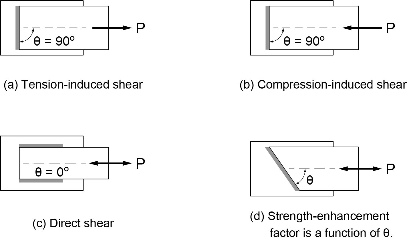
Figure 1
Shear in Fillet Welds
Question 2: Is fire protection required for bracing members, or is it mainly columns and floor assemblies?
Answer: The answer is found in Fire Facts for Steel Buildings by R.G. Gewain, N.R. Iwankiw, F. Alfawakhiri and G. Frater (CISC, 2006), which states on page 33: “Column fire ratings are used not only for actual building columns, but also are applied to other members that are principally designed for axial loads, such as truss members and bracing.”
This publication is available as a free download on the CISC website:
https://www.cisc-icca.ca/product/fire-facts-for-steel-buildings/
Question 3: According to S16-14, connections in conventional construction are designed for the factored seismic forces based on Rd = 1.5 and Ro = 1.3, for building heights ≤ 15 m. However, the National Building Code of Canada (NBC 2015) states that connections must be designed so as not to yield. Is there a discrepancy here?
Answer: What the NBC 2015, Article 4.1.8.15.(1), refers to are diaphragm connections (e.g., deck collector connections, deck welds, etc.) and not connections of primary framing members such as bracing connections in seismic force-resisting systems. Some yielding of the bracing connections in conventional construction can be expected, but the failure mode must be ductile (otherwise they must be designed for the gravity loads combined with the seismic loads multiplied by Rd) when IE Fa Sa(0.2) > 0.45, according to S16-14 Clause 27.11. Also, connection forces need not exceed the grosssection strength based on the probable yield stress, Ry Fy. A discussion on what constitutes a ductile failure mode can be found in the Commentary to Clause 27.11 in Part 2 of the Handbook of Steel Construction.