Seismic Corner – Issue No. 51
This article discusses the ductile brace-end rotation requirements for Type MD and some of Type LD braced frames.
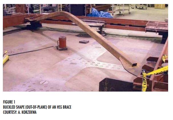
Well-proportioned concentrically braced frames exhibit ductile behaviour through yielding and buckling of the braces. When a compression brace buckles, local bending or plastic hinging occurs in three locations – the ends and the mid length, as shown in Figure 1. In order to allow plastic hinging at the ends, either the connections or the body of the brace near the ends should accommodate the hinge rotation and load reversal without fracture.
S16 requirements
The end connections of the braces in moderately ductile concentrically braced frames (Type MD CBF) are required to be proportioned and detailed for ductile hinge rotation. Alternatively, these connections may be designed with larger flexural resistance than the brace (as capacity-protected elements), thereby forcing plastic hinging in the brace. These requirements also apply to limited-ductility concentrically braced frames (Type LD CBF) except where the specified short-period spectral acceleration ratio is less than 0.55 and the brace slenderness ratio exceeds 100. In any case, they do not apply to braced frames in conventional construction.
Design process
The designer of the structure selects the brace section and cross-section orientation, which determine the governing plane of buckling. The governing plane of buckling, out-of-plane or in-plane, dictates the brace connection configuration and details. Conversely, several factors, including the connection size and configuration, affect the actual brace length, which should be taken to be the design brace length. Hence, the structural designer must estimate the approximate size and configuration of each end connection before arriving at the design brace length. The plane of buckling and the corresponding brace length, among other things, must also be specified so that the connection designer can provide an appropriate connection design.
Now, what are the connection configurations, details and their options?
HSS braces
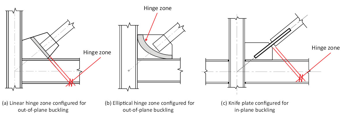
Since HSS are the most popular choice for braces in Type MD and Type LD frames, we will focus on connections for HSS braces. Typically, a hinge zone is provided (a) in the gusset plate when out-of-plane buckling governs the design of the brace, or (b) in a knife plate when in-plane buckling governs (see Figure 2). The hinge zone must be free to rotate without hindering brace buckling in the governing buckling plane. Stiffeners and other objects that may restrict this free rotation, including the floor slab, must be kept clear of the hinge zone. NEHRP provides a detailed description for three connection configurations in its publication, Seismic Design Technical Brief No. 8.
Out-of-plane buckling
Figure 2a shows the most popular approach, which has been adopted from the research work reported by Astaneh-Asl et al (1986). In this configuration, the hinge zone is a band that runs perpendicular to the axis of the brace. The width of this linear hinge zone should be equal to or greater than 2tg where tg is the gusset plate thickness. In order to provide this unrestrained hinge zone, the brace must be shortened, resulting in a larger gusset plate – especially when a rectangular gusset is used.
The extended gusset and the unstiffened hinge zone also lead to the need for a thicker plate for compressive resistance.
Recent studies by Roeder et al (2011) suggest an alternative detail, which features an elliptical hinge zone that is 8tg wide, as shown in Figure 2b. Other restrictions also apply. This detail allows the use of smaller and thinner gussets. Block shear (pull out), instead of buckling of the gusset, usually controls the design. The elliptical hinge connections behaved well in the tests reported by Roeder et al.
In-plane buckling
Figure 2c shows the configuration that features a knife plate, perpendicular to the gusset. The hinge zone in the knife plate is located within a band having an unrestrained width of three times the knife plate thickness. This detail allows the brace end rotation required for in-plane buckling.
Alternatively, the connections may be designed with a larger flexural resistance than the brace instead of a ductile hinge zone. This approach is quite onerous when out-of-plane buckling governs the design.