Two methods are provided in CSA Standard S16-14, to determine the factored compressive resistance, Cr, for sections that exceed the width (or diameter)-to-thickness ratios specified in Table 1 of the S16-14.
These are the effective area method and the effective yield stress method.
Effective Area Method
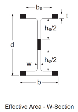
Engineers are generally familiar with the concept of effective area when designing columns subject to elastic local buckling. Such sections are expected to undergo local buckling before reaching the yield load in axial compression, AFy. They are designed in accordance with CSA S16-14 Clause 13.3.5 (a) whenever the width-to-thickness ratio of the flanges or web exceeds the limits given in Table 1 of S16-14. When calculating the axial compressive resistance, a portion or portions of the cross-section is considered ineffective and is therefore omitted. Considering a wide-flange section, for example, the effective cross-sectional area, Ae, is computed as follows: If the flanges exceed the maximum width-to-thickness ratio of Table 1, the area of the tips (shaded parts in the figure shown) is removed, such that the remaining effective flange width, be, meets the maximum ratio; similarly, the effective web depth is taken as he as shown in the figure. The effective portions of the flanges and web together make up the effective area, Ae.
Effective Yield Stress Method
Perhaps less familiar is the effective yield stress method, which S16-14 also permits for calculating the axial compressive resistance. According to this concept first introduced in S16-01, the cross-sectional area remains intact, but the yield stress is reduced to account for local buckling. The effective yield stress, Fye, is taken as the reduced yield stress determined from the width-to-thickness ratio meeting the limit in Table 1. If both the flanges and the web are subject to elastic local buckling, two separate effective yield stresses are calculated. For simplicity, the member resistance is based on the lower of the two values.
The effective area method and the effective yield stress method, in general, do not give the same answer. An example is presented below to illustrate both methods. Consider a laterally supported W360x72 column (L = 0) made of ASTM A992 steel. The cross-sectional area is A = 9100 mm2 and the specified yield stress, Fy, = 345 MPa. The factored axial compressive resistance will be determined on the basis of (1) effective area and (2) effective yield stress.
(1) Effective Area Method
Check the width-to-thickness ratios of the flanges and web:
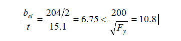
The flanges are not subject to local buckling.
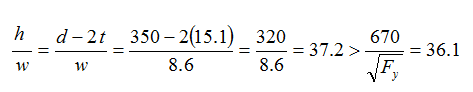
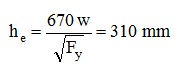
The web is subject to elastic local buckling. The effective web depth is given by:
The effective area is: ![]()
And the compressive resistance is: ![]()
(2) Effective Yield Stress Method
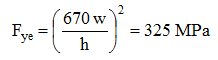
The effective yield stress is based on the maximum width-to-thickness ratio of the web:
And the compressive resistance is given by: ![]()
Although only the web is subject to local buckling, the entire cross-section is affected by the reduced yield stress. For this reason, the effective area method results in a greater resistance (for a laterally braced member) than the effective yield stress method, in this particular example. However, the effective yield stress method usually gives a larger resistance for slender members.
For both methods, the elastic buckling stress, Fe, is determined using gross section properties.
In the CISC Handbook, both methods are used to calculate the factored compressive resistances, Cr, for W-columns subject to elastic local buckling, and the tabulated values are the larger of the two. Only the effective area method is used to calculate the Cr values for other columns and struts, except for a small number of square HSS for which the effective yield stress method was used and which are identified accordingly.