
Dr. Muntasir Billah, P.Eng.
Assistant Professor, Department of Civil Engineering, Lakehead University
Column base plate connections, typically consisting of a steel member welded to a steel base plate connected to the concrete base via anchor rods and grout, are commonly found in building and non-building structures.
This base connection is one of the most important structural components which acts as a transfer medium for all the forces and moments from the entire building into the foundation. Failure of these base plate connections can result in the collapse of the entire frame as it affects the ductility demand and force distribution in the structure (Grauvilardell et al., 2005). After the 1994 Northridge Earthquake, design of steel connections has been significantly revamped across north America. However, a significant amount of effort has been dedicated to the steel beam-column connections under seismic loading. In comparison, limited experimental and numerical investigations were devoted to study the behavior of column base connections. As a result, the design of a column base connection presents several issues, which is not limited to characterization of force and deformation demands, characterization of deformation capacities of the connection components and failure mechanisms, and development of desirable hierarchies of failure modes (Gomez et al., 2010).
Most of the previous studies and design guidelines are focused on base plate design under axial load and uniaxial bending moment (typically major axis). However, very often these base plates are subjected to bidirectional bending moment from lateral loads such as wind and earthquake. Current design codes and guidelines do not address the design of these exposed base plate connections under axial load and bi-axial bending. Although, the columns are designed and checked under combined axial load and bi-axial bending, when it comes to the base plate connection, only the axial load and major axis bending are considered. Practicing engineers often adopt complex finite element methods, or design them in the two directions separately, which often results in overly conservative design.
Currently, there exists a gap in the research to develop a design guideline for exposed column base plate connection under combined axial load and bi-axial bending. The overarching objective of this research is to develop a simplified design guideline for exposed column base plates under combined axial load and bi-axial bending. This will be achieved through the pursuit of the following objectives: (i) finite element simulation of base plates under combined axial load and bi-axial bending, (ii) experimental investigation of column base plates under combined axial load and bi-axial bending, (iii) comprehensive parametric study to identify the parameters that influence the behavior of exposed column base plates, and (iv) developing interaction equations, design methods, and simplified tools for practicing engineers.
PRE-TEST ANALYTICAL STUDY AND FINITE ELEMENT ANALYSIS:
This pre-test analytical study is conducted to investigate the performance of column-base connections under axial load and uniaxial bending. The purpose of this analytical study is to select and validate a suitable modeling strategy that can mimic the experimental response of column-base connections with reasonable accuracy. For pre-test analytical study, a 3D finite element model is developed using ABAQUS simulation platform. In order to validate the accuracy of the adopted modeling techniques and material models, the results from FE model is compared with the experimental results from Gomez et al. (2010) (large scale experiment test no. 1). This specimen was tested monotonically without any axial (gravity) load and having 10.6% peak column drift. Fig. 1 shows the comparison of the experimental and numerical results in terms of anchor rod force and column drift. From Fig. 1, it can be concluded that the developed numerical model can very well predict the experimental results with reasonable accuracy. The maximum anchor rod force is found 220.12 kN and 213.24 kN for the experimental and numerical results, respectively having a 3% difference between them.

Fig. 1: Comparison of experimental and numerical results
BASE CONNECTION RESPONSE UNDER UNIAXIAL AND BIAXIAL BENDING:
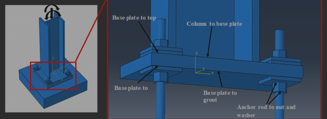
As the first phase of this research, column-base connections are numerically investigated under combined axial load and bi-axial bending. Fig. 2 schematically represents the FE model and the applied loadings. Tie constraints are provided between the column and base plate, anchor rod, nut and washer and grout and concrete since they have monolithic properties. Surface to surface contact interactions are defined between the interface of base plate-grout, base plate and both the top and bottom washer and anchor rod-base plate with finite sliding formulation. Two different interaction properties are defined for these surface to surface interactions. Contact details between the elements are also shown in Fig. 2.
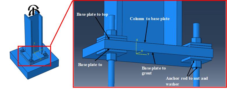
Fig. 2: Overview of the finite element model
Column behavior: To represent the gravity load, an axial load equal to 30% of the column capacity was applied as an axial compression. For uniaxial monotonic loading, a lateral drift of 10.6% was applied along the strong axis direction of the column whereas for biaxial loading, additional 4.9% drift was introduced towards its weak axis direction in addition to the axial compression. Column subjected to biaxial loading suffered considerable out of plane local buckling near its base compared to uniaxial loading. This occurred due to localized compression as well as not having sufficient thickness of the web and flanges to resist weak axis bending. From Fig. 3, it can be seen that the stresses are concentrated near the column base when subjected to uniaxial loading. However, for biaxial loading (Fig. 4), the stresses are spread along columns height up to half of its total length due to an angular resultant displacement caused by simultaneous bidirectional loading. Maximum stress of the column is found to be 3% higher for biaxial loading compared to the uniaxial loading.
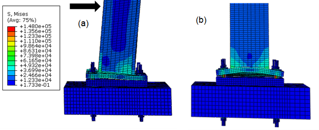
Fig. 3: Column stress (Von mises) along (a) weak axis and (b) strong axis under uniaxial loading
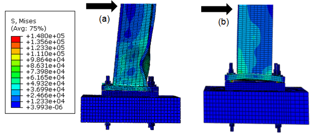
Fig. 4: Column stress (Von mises) along (a) weak axis and (b) strong axis under biaxial loading
Base plate behavior: Identifying yield lines in the base plate of deformed base connections is important and can be a difficult task. Current AISC design guideline assumes the yield line forms in parallel with the flange of the column. Detailed experimental program conducted by Gomez et al. (2010) revealed that yield lines develop in inclined patterns under uniaxial bending. Similarly, the FE model showed development of inclined yield lines on the tension side of the base plate (Fig. 5a) under uniaxial loading. This can be attributed to the resistance to the tensile force by the anchor rods causing a curve shaped deflection at the tension end. A straight yield line is formed beneath the column flange on the compression side of the plate (Fig. 5a). Under biaxial loading, yield line is critical near the anchor rod which is in tension during both loading direction (Fig. 5b). There is also a formation of yield lines under the column flange across the width on the other side of the base plate extending to the edge of the base plate (Fig. 5b). Maximum stress is found to be 4% lower in case of biaxial loading compared to uniaxial loading since there is alternative tension-compression behavior under biaxial loading.
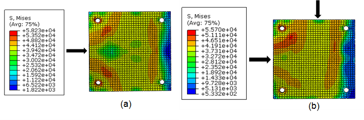
Fig. 5: Base plate behavior under (a) uniaxial and (b) biaxial loading
PLANNED EXPERIMENTAL PROGRAM:
With the financial support of CISC, an extensive experimental program will be conducted on six reduced scale exposed-type steel column base plate connections in Summer 2020 to establish the design methods and interaction equations for column base connections under combined axial load and bi-axial bending. Two steel HSS columns and four steel wide flange columns (W-section) will be welded to the center of the base plate. The column size, as well as width-thickness ratio, will be selected to prevent yielding and local buckling of the column before failure of the base connection. The thickness of the baseplate for the HSS columns will be kept constant while two different base plate thicknesses will be considered for wide flange columns in the experimental study. The proposed test setup is shown in Fig. 6.
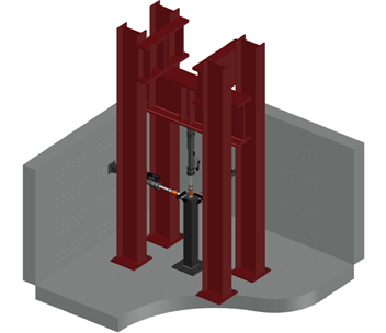
Fig. 6: Proposed experimental setup for column-base plate connection testing
NEXT STEPS: The next step in this ongoing research is to perform experimental investigations on column-base connections under combined axial load and bi-axial bending. This research will be critical to potentially improve base plate and anchor rod design with accuracy and economy under multi-axial loading. All the specimens have been designed and are currently being fabricated. Detailed experimental testing will be done in summer 2020.
References
Grauvilardell, J.E., Lee, D., Hajjar, J.F., and Dexter, R.J. (2005), “Synthesis of Design, Testing and Analysis Research on Steel Column Base Plate Connections in High Seismic Zones,” Structural Engineering Report, No. ST-04-02, Department of Civil Engineering, University of Minnesota, Minneapolis, Minnesota.
Gomez, I.R., Kanvinde, A.M., and Deierlein, G.G. (2010), “Exposed Column Base Connections Subjected to Axial Compression and Flexure,” Technical Report submitted to the American Institute of Steel Construction, AISC, Chicago, Illinois.