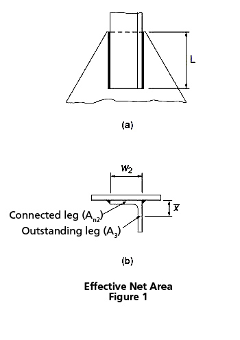
The effect due to shear lag in a tension member is usually accounted for by means of an effective area method. For weld-connected members, Clause 12.3.3.3 of CSA S16-14 applies to members of various cross sections in general. When only one leg of an angle tension member is attached to its end supports, with longitudinal fillet welds, the cross-section area of the angle is divided into two components, i.e., the attached leg and the outstanding leg. Figure 1(a) shows an angle connected by a pair of longitudinal welds of length, L. For the attached leg, shear lag is a factor when L ≤ 2w2. In accordance with Clause 12.3.3.3 (b)(ii) and (iii), its effective net area, An2, as shown in Figure 1(b), is determined based on the weld configuration and, for short welds, also the leg thickness.
The effective net area of the outstanding leg, An3, is calculated according to Clause 12.3.3.3(c). Its shear lag effect is given as a function of the ratio of the eccentricity of the weld with respect to the centroid of the outstanding leg, x, to the weld length, L (for long welds). Then the tensile resistance of the member is calculated in accordance with Clause 13.2(a)(iii) using the total effective net area of the angle section, Ane = An2 + An3.
Further information may be found in the CISC Commentary on CSA S16-14 in Part 2 of the Handbook of Steel Construction.