

By Charles Albert, P.Eng.
CISC provides this column as part of its commitment to the education of those interested in the use of steel in construction. Neither CISC nor the author assumes responsibility for errors or oversights resulting from the use of the information contained herein. Suggested solutions may not necessarily apply to a particular structure or application and are not intended to replace the expertise of a licensed professional engineer or architect.
Question 1: What is the buckling resistance of a compression member when only one flange is laterally braced?
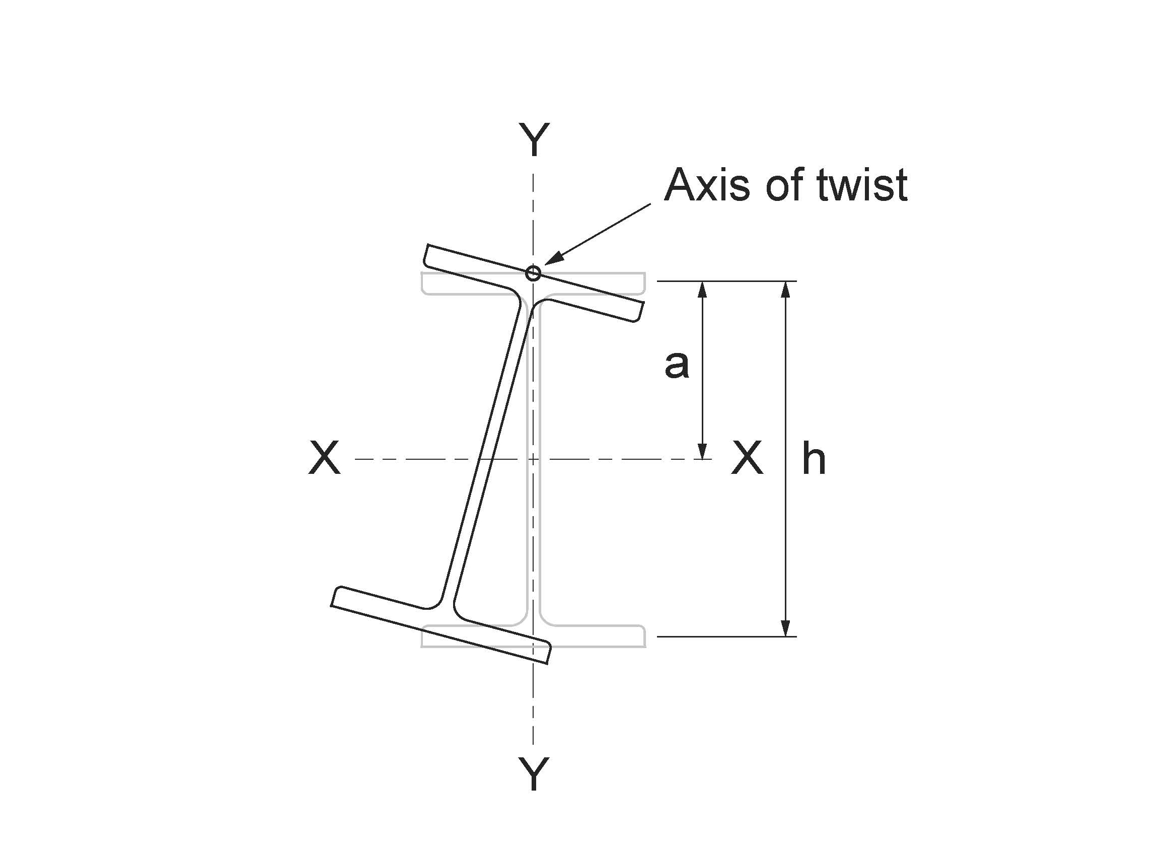
Figure 1
Torsional-Flexural Buckling About a Constrained Axis
Answer: Although this condition is not covered in CSA S16-14, it occurs mainly in two situations: (1) exterior columns in single-storey buildings, and (2) beams in braced frames supporting a steel deck. In case (1), the outside flange of the column is laterally braced by girts while the inside flange is unsupported. In case (2), the top flange of a roof beam, for example, is continuously braced by the deck while the bottom flange is unsupported. In both cases, torsional-flexural buckling under axial loading occurs about a constrained axis of twist located near the braced flange, as shown in Figure 1.
Ziemian (2010) provides a formula for the elastic buckling load:
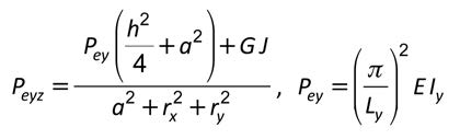
where:
a = Distance between the constrained axis and the shear centre of the member
G = Shear modulus
h = Distance between the flange centroids
Iy = Weak-axis moment of inertia
J = St. Venant torsional constant
Ly = Unsupported member length between points of zero twist
Pey = Euler (flexural) buckling load about the weak axis
rx , ry = Principal radii of gyration
Question 2: : How is the formula for Mu in S16-14 Clause 13.6(e) applied to a WT-section in bending with the stem in compression? And what value of βx should be used?
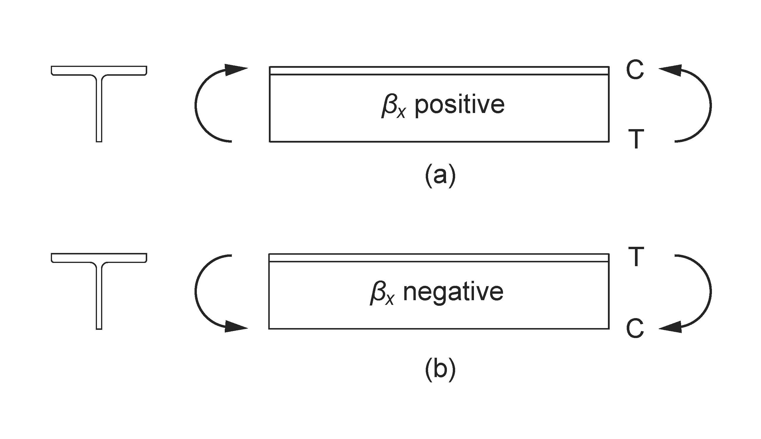
Figure 2
Laterally Unsupported WT-Section
Answer: The same formula for the elastic buckling moment, Mu , is used whether the WT stem is in compression or tension. The only difference is that the asymmetry parameter, βx, is taken to be (a) positive when the flange is in flexural compression, and (b) negative otherwise (i.e. when the stem is in flexural compression), as shown in Figure 2. In case (b), the WT-section is less stable, and Mu will therefore be smaller than in case (a).
The values of βx listed in Part 6 of the Handbook of Steel Construction were calculated for WT sections using the exact expression given in Part 2 (CISC Commentary on CSA S16-14) and are the most precise. The formula for βx in Clause 13.6(e), on the other hand, is an approximation for singly-symmetric beams which may be used in the absence of more accurate values.
*This article was originally published in Advantage Steel no. 66 and can be found here.