
CISC provides this column as part of its commitment to the education of those interested in the use of steel in construction. Neither the CISC nor the author assumes responsibility for errors or oversights resulting from the use of the information contained herein. Suggested solutions may not necessarily apply to a particular structure or application and are not intended to replace the expertise of a licensed professional engineer or architect.
Question 1: What are the different grades of steel covered in ASTM A709?
Answer: ASTM A709 steel is used mainly for bridges and has been referenced in CSA S6 since the 2014 edition. It is an “umbrella” standard that includes the grades listed below. For each designation, the first number indicates the minimum specified yield stress, Fy , in ksi, and the second number [in brackets] in MPa.
▪ 36 [250] – Corresponds to ASTM A36/A36M.
▪ 50 [345] – Corresponds to ASTM A572/ASTM A572M grade 50/345.
▪ 50S [345S] – Has a maximum yield stress and a maximum yield-to-tensile ratio, useful for seismic applications. It corresponds to ASTM A992/A992M and is generally available in shapes.
▪ 50W [345W] – Has enhanced atmospheric corrosion resistance (weathering steel). This grade corresponds to ASTM A588/A588M.
▪ HPS 50W [HPS 345W], HPS 70W [HPS 485W], HPS 100W [HPS 690W] – High-performance steels with low carbon content, resulting in improved weldability, toughness and corrosion resistance. These grades are available in plates only.
▪ 50CR [345CR] – Stainless steel with improved corrosion resistance. It corresponds to ASTM A1010/A1010M.
When notch-tough material is required, ASTM A709 grades can be ordered with the addition of a suffix to specify the type of tension component (“T” for non-fracture critical or “F” for fracture-critical). And for each type of component, the impact testing temperature zone (1, 2 or 3) is specified.
Question 2: When loading is applied on the top flange of an unbraced beam segment, CSA S16:19 Clause 13.6.1(a) states that the destabilizing effect can be taken into account using a rational analysis. Could you provide a reference?
Answer: When loading is applied above the shear centre, a destabilizing moment (P x a) is induced as the cross-section rotates during lateral-torsional buckling, decreasing the beam’s moment capacity. A typical situation involving gravity loading on a floor beam is illustrated in Figure 1(a). This generally occurs during construction while the top compression flange is not yet braced by the deck.
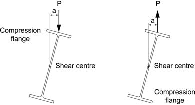
(a) Gravity Loading (b) Wind Uplift
Figure 1
The elastic buckling moment may be determined according to “Lateral Buckling of Beams”, J.W. Clark and H.N. Hill, ASCE Journal of the Structural Division, Vol. 86, July 1960:
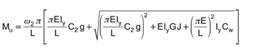
Equation 1
where ω2 = 1.13 and C2 = 0.45 for simply-supported beams with uniformly distributed loading. The magnitude of “g” is the vertical distance between the shear centre and the point of application of the load, or d/2 where “d” is the beam depth. For gravity loading, the sign of “g” is negative when loading is applied above the shear centre.
Another common situation involves wind uplift on a roof beam, as shown in Figure 1(b). In this case, the unbraced bottom flange is in compression, and the upward load on the top flange exerts a stabilizing effect. The sign of “g” in Equation 1 would then be positive, increasing the moment resistance.
Alternatively, S16:19 provides a simple (although conservative) method to account for the destabilizing effect by using ω2 = 1.0 and C2 = 0, and an effective unbraced length of 1.2L for flexurally simply-supported ends or 1.4L for other end restraint conditions.