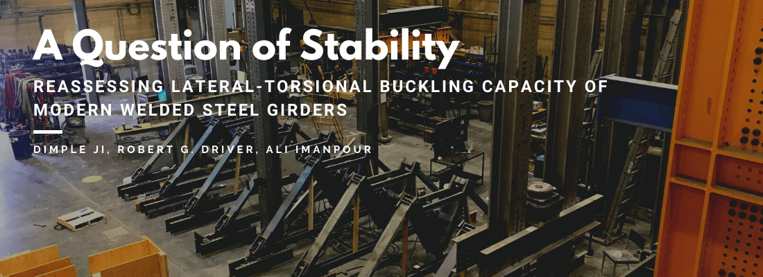
Reassessing Lateral-torsional Buckling Capacity of Modern Welded Steel Girders
Dimple Ji, Robert G. Driver, Ali Imanpour
Lateral-torsional buckling is a potential failure mode of steel girders. Under flexural bending, it involves the vertical movement, then simultaneous horizontal sway and rotation of a girder within an unbraced span. Visually, this results in a girder with a twisted appearance.
The Canadian steel design standard, CSA S16, prescribes provisions to determine lateral-torsional buckling capacity by means of a unified curve that identifies three major regions of behaviour: elastic lateral-torsional buckling, inelastic lateral-torsional buckling, and full cross-sectional capacity. The current design equations were introduced in 1974 and apply to both rolled and welded sections. Though there have been slight modifications, the root equation has remained the same since then. The basic premise is relatively simple; for a given girder cross-section and unbraced length, the flexural capacity must exceed the bending moments induced by the design loads. However, this is with the assumption that we understand the lateral-torsional buckling behaviour of steel girders and the current design equations can properly predict the flexural capacity of the member. In fact, concerns have been raised that the existing provisions may be unconservative for welded sections.
The cause of concern lies in the nature of welded sections and their residual stresses, which are inherent stresses created in girders during the production process. Though residual stresses exist in both rolled and welded sections (Figure 1), the welds in the latter produce residual stress distributions that may cause them to be more susceptible to lateral-torsional buckling. Specifically, this refers to the compressive stresses in the compression flange tips. Because the compression flange contains pre-existing compressive residual stresses, yielding can occur well before the full yield stress is applied to the section. As welded sections possess larger regions of compressive stress, there may be significant losses of the compression flange stiffness and rapid decreases in the flexural bending capacity.
Recent numerical studies by Kabir and Bhowmick echo these sentiments and have implied that the existing design curve is unconservative for welded sections, particularly in the inelastic lateral-torsional buckling region where residual stresses may significantly affect the capacity of such girders. A 2011 study by well-known researchers MacPhedran and Grondin recommended that the existing provisions be revised to consist of two separate girder design curves – one for rolled sections and the other for welded sections, similar to the approach adopted in Eurocode 3.
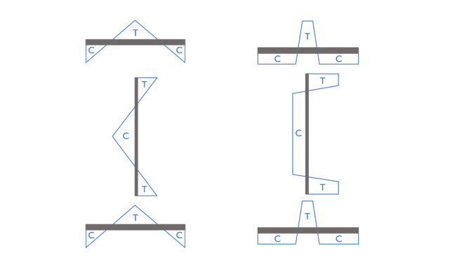
Figure 1: Residual stress distribution in rolled (left) and welded (right) girders; T = tension, C = compression (Unsworth 2018)
As reducing predicted design strengths for welded girders could increase their cost significantly, it is prudent to further assess the situation. While recent research may suggest concerns with the existing design curve, it is important to note that these studies have been performed using numerical methods or have utilized data from physical testing conducted mainly in Japan in the 1960s to 1980s. Since then, manufacturing and fabrication processes have changed significantly, which is likely to have a considerable effect on residual stress amplitude and distribution, and therefore flexural bending capacity. Moreover, these processes vary from country to country; girders tested in Japan may not necessarily be representative of those fabricated in Canada. Therefore, it seems to be in the steel industry’s best interest to conduct further studies before we adopt or reject modifications to the existing design provisions.
The CISC Centre for Steel Structures Education and Research (Steel Centre) is an education and research network at the University of Alberta that aims to conduct research closely aligned with industry needs. The Steel Centre has launched a research program to investigate lateral-torsional buckling in welded girders and address the gaps in literature. In response to the lack of recent physical testing, one of the research projects is focused on investigating the stability response of modern welded girders using large-scale testing. The girders will span approximately 10 m in length, with flange widths ranging from 300 to 470 mm and section depths of 600 to 900 mm – representing girders commonly used in building applications and comparable to small or half-size bridge girders. Girders are simply supported in-plane and torsionally pinned, with eight concentrated loads applied at the top flange (Figure 2). The only lateral support provided is at the ends of the girder, meaning it is free to buckle along its 10 m unbraced length. Nine unique cross-sections and a total of 11 tests are planned; all girders are produced with modern manufacturing and welding processes.
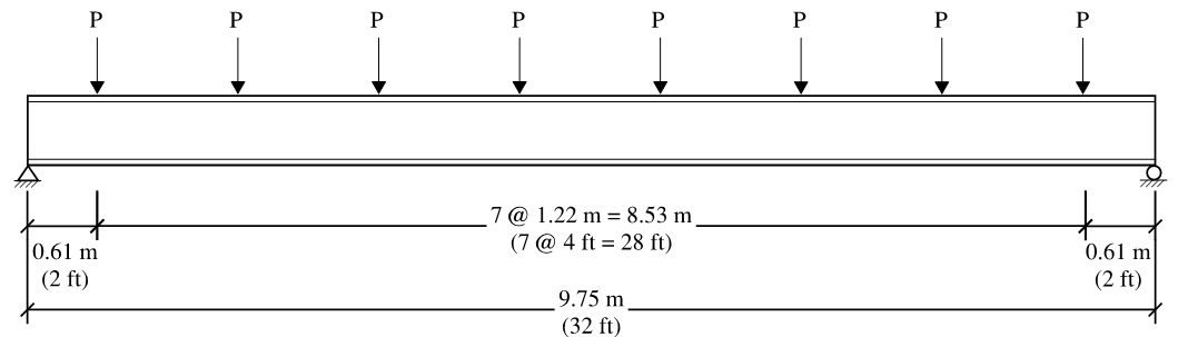
Figure 2: Girder dimensions and loading scheme.
The design of a testing bed capable of accommodating the large girders, as well as the displacements and rotations expected during lateral-torsional buckling, posed a substantial challenge. An early obstacle was determining a way to allow lateral sway of the test girder while maintaining vertical load, which is difficult to achieve and a major reason for the paucity of lateral-torsional buckling testing completed. The solution involves gravity load simulators, a unique pin-jointed loading apparatus originally developed at Lehigh University for testing specimens permitted to sway. The pinned connections allow the girder to sway freely in the lateral direction, while keeping load application close to vertical (Figure 3). No manual adjustments are necessary and the apparatus can sway from the equilibrium position in either direction. By using a gravity load simulator to apply each of the eight loads, any lateral girder movement can be accommodated with close to zero restraint.
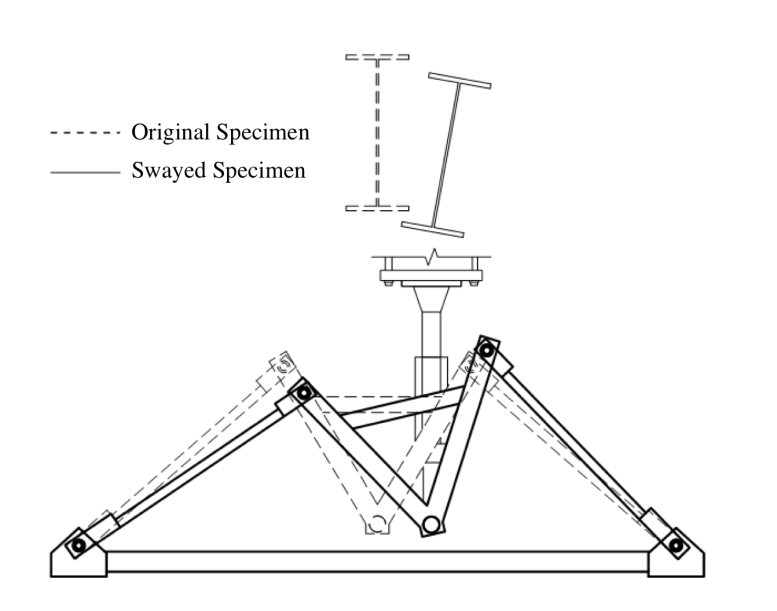
Figure 3: Gravity Load Simulator
The load application challenge, among many others, has been overcome and the testing bed design is complete (Figure 4). A look inside the I.F. Morrison Structural Engineering Laboratory at the University of Alberta reveals a sizable footprint as preparations for testing are underway. The set-up occupies an area of 11 m x 5 m and extends as high as 4 m. Excitingly, it will be the first lateral-torsional buckling test of this magnitude! Upon its successful completion, the research will contribute important new experimental results to an otherwise aging database of tests and comment on the adequacy of the S16 provisions. Through an improved understanding of lateral-torsional buckling, the research results will give engineers increased confidence in the design of safe and efficient modern welded girders.
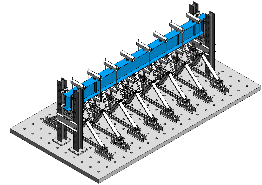
Figure 4a: Setup for lateral-torsional buckling test
Figure 4b: Setup for lateral-torsional buckling test (see attached photo)
This research project is another example of the benefits of the close partnership the Steel Centre has forged with the Canadian steel industry. Steel Centre and CISC member Supreme Group is providing all fabrication for the girders and the ancillary testing fixtures, along with extensive expertise in bridge girder fabrication, and SSAB has generously provided all the plate material required for the girders. This support for applied research that benefits the steel industry is greatly appreciated.