(Photo credits: Peter Soland. The article is based on information and content provided by Peter Soland & Consultants SMi)
Manufacturer: Central Welding & Iron Works
Detailer: Genifab Consultants
Consultant: Les Consultants SMi
Contractor: Roxboro Excavation
Owner: Ville de Montréal (Major Projects)
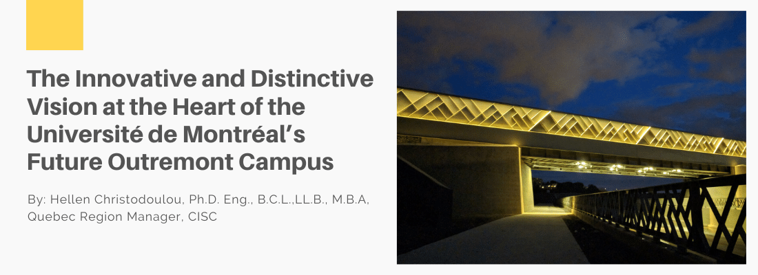
In 2013, the Université de Montréal, one of the main universities in the Montreal metropolitan area, began the construction of its new MIL campus in Outremont, located on the deserted grounds of the former Canadian Pacific rail yards. Before proceeding with the work, it was necessary to improve access to the site and move two tracks of the former railway network from the south to the north.
Wishing to demonstrate its architectural vision in an exceptional project, the city imposed exacting standards on the quality of the work and lighting. This goal will be realized by transforming a simple railway bridge into an object of beauty that everyone can admire.
The first stage of construction will be the creation of a new railway bridge that will allow for urban and institutional development in the cleared areas. The railway bridge will pass over the new street running between Durocher Avenue and the future extension of Outremont Avenue. It will be a steel single-span bridge on concrete abutments.
“There is so much to learn about urban railway bridges, both for us as designers and for the public. A contemporary design engineer must dare to see railway bridges beyond their structural concept and functionality. Bridges need to be redesigned and imagined as integral elements of our cities, districts, and everyday lives. At the start of each design project, we need to remind ourselves that we have an opportunity to create something more than a bridge to carry trains.” Petrica Voinea, Eng., M.Eng. Director, Asset Management, PJCCI (formerly SMi).
The type of structure was selected based on the following criteria:
- There must not be any obstruction between the traffic lanes of the boulevard beneath the underpass, which means that there must not be a central pillar, but rather a single longer supporting structure.
- Optimize as best as possible the boulevard decline and minimize the railway embankment elevation.
- Respect a minimum clearance of 5 m between the top of the boulevard and the underside of the overpass.
- Ensure that the simplest construction and installation methods are employed.
The final structural design for the bridge was chosen according to the following criteria:
a. Respect of visibility (factor K)
The borough of Outremont enforces a 40 km/h speed limit on its roads. The preliminary study, supplied for information purposes, was prepared using this speed limit plus a margin of 10 km/h as a safety factor.
After analyzing different bridge deck thicknesses and possible clearance heights of several profiles affecting the final level of the roadway, the K factor was calculated depending on the two reference speeds. Note that the K factor must be at least 12 for a speed of 50 km/h and 17 for a speed of 60 km/h. The final solution that was applied allows a K factor of 16.08.
b. The geometry of traffic routes beneath the bridge and pedestrian footpath (sidewalk)
The layout and geometry of the bridge must allow the following:
- A sense of safety and comfort for all users (pedestrians, cyclists, and drivers),
- An unobstructed view for pedestrians and cyclists,
- Snow removal on the bike path and sidewalk.
The bridge’s structure, lower-level passage, and supporting walls must be designed to create an agreeable and safe space for pedestrians, cyclists, and drivers travelling through the lower-level passage of the central axis. An innovative visual concept must be designed for these walls to make the lower-level passage and the outside areas adjacent to the supporting walls more user-friendly.
After analyzing the situation, the structure best suited to these compulsory criteria is a TPG deck (through-plate girder) which has been selected for the future railway overpass (see Fig. 1).
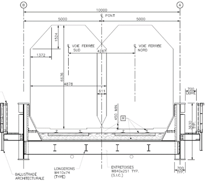
Figure 1
Given the significant dead loads (630 tonnes) and presence of two railway vehicles (Cooper E90), which account for approximately 1520 tonnes, the main beams are of considerable size (3650 mm in height, Figure 1) and are supported by a horizontal and vertical brace system.
Internal knee braces are incorporated in each of the main beams to support the top of the beam and the ballast platform.
The overpass, approximately 27.76 m long and 10.0 m wide, supports two railway tracks installed on a ballasted steel deck (the rails are attached to wooden crossbeams that rest in the ballast) to ensure that this section on the overpass has the same track conditions as the adjacent embankments (see Figure 2).
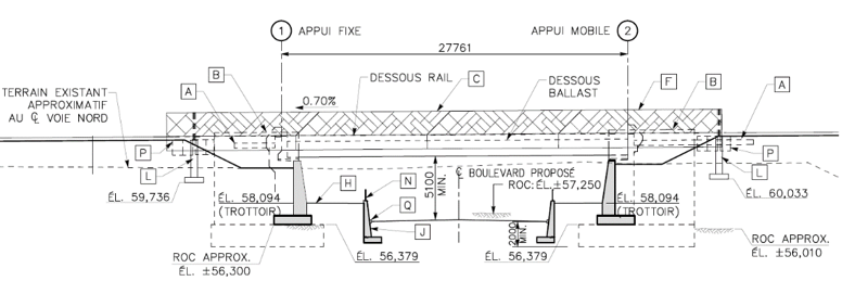
Figure 2
c. Total construction costs of project
Costs of tender: 9.5 million
d. CP design requirements
The overpass has been designed in accordance with the North American AREMA railway standard and adheres to the CP Design Guide.
-
Load and load combinations for design
- Standards: AREMA
- Canadian Pacific Guidelines
- Vehicle: Cooper E90
-
Elevation of top of rails at the centre of the bridge
The railway bridge is to be constructed and maintained by the City of Montreal and, in return, the ballast and rails resting on the bridge will be constructed and maintained by CP. Elevation to be observed at the bridge entrance is 63.84 m (entrance) and 63.65 m (exit) with a slope of approximately 0.7%.
-
Distance between the centre lines of the parallel rail tracks
The distance to be observed on the railway bridge between the centre lines is 14 feet (4267 mm), which does not allow a dual-span bridge as the space between the two tracks is not sufficient to install beams. The bridge must be constructed as a single-span structure containing the two railway tracks.
-
Clearance height
CP has accepted that clearance beneath the structure will be reduced to 5.1 m provided that the City implements adequate signage in the vicinity to prohibit trucks or limit vehicle height.
Given the geometry of the railway trajectory in relation to the boulevard it crosses, the overpass deck has a pronounced angle of approximately 27.4°.
The weight of the rails, crossbeams, and ballast together with the loads of the railway vehicles are transferred onto the steel floor system, which is connected to crossbeams (braces) spaced at 700 mm, which in turn are supported by two main beams. For the two ends of the overpass, the layout of the braces, their dimensions, and their interconnections have been adjusted to take into account the specific load distribution resulting from this angle (see Figure 3).
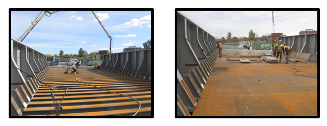
Figure 3
The ballasted tracks protect the overpass’s steel floor system adequately against potential damages caused by derailed cars and protect the public on the street below from falling ballast or material coming from the railway or maintenance operations.
The detailed engineering company Genifab also participated in this project and generated a 3D model of the steel structure with details of the structural elements. Genifab also prepared drawings for erecting the steel structures on site.
For railway maintenance and inspection purposes, the deck is equipped with two inspection walkways, one on each side. With the assistance and collaboration of the architect, the designers replaced the walkway railings with two architectural balustrades. The overpass is supported by two reinforced steel abutments that are integrated in a unit with supporting walls rising from the sidewalks that extend along the street (see Figure 4).
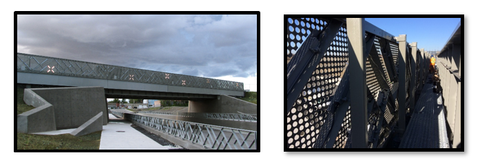
Figure 4
The use of steel accentuates the structure’s railroad history. The architectural balustrade will blend with and accentuate the features of the steel structure.
e. Integration of structure in the environment
The excavation work has reshaped the site’s topography by integrating the abutments and the architectural supporting walls on which the new overpass rests. The architectural and environmental approach favours a structure that is both understated and striking, with the aim of integrating the structure in its environment, its history, and the future of its neighbourhood.
This project will make it possible to improve access to the eastern side of the site by constructing a passage beneath the new railway corridor to integrate the geometry and specific features of the new bridge. Likewise, it aims to reflect the objectives of consolidating the territory contained in the City of Montreal’s urban development plan as well as municipal expectations for developing surrounding areas.
The incorporated artistic elements and the development plan define an area that is incongruent with the strict organization of the campus and the city in general. The geometry is inspired by the former oblique axis of the shunting yard. The interaction between concrete and landscape aims to alter your visual perception and phenomenological experience when approaching the bridge. It also allows to incorporate the intersecting pedestrian walkways leading to other points on campus. By increasing the number of pedestrian walkways alongside the railway structure, the plan creates a more dynamic urban environment that goes beyond a simple linear progression extraneous to the work of art (see Figure 5).
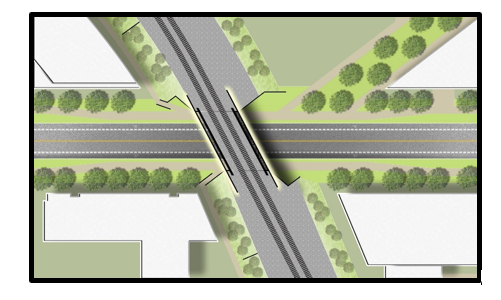
Figure 5
The walls of the abutment and the supporting walls of the banks will be made of poured concrete. Particular attention will be paid to the architectural details, the aesthetic qualities of the surfaces, and the integration of steel elements reflecting the main structure of the bridge (see Figure 6).
SMi has teamed up with Civiliti for the architectural component and the lighting. This first collaboration between architects and designers from this Montreal-based company was a marked success for the new railway bridge. The new bridge earned them the Lighting award and Non Categorized award at the 10th edition of the Grands Prix du Design.
“The architecture and lighting of the new bridge reflect both the movement and vital force that we associate with trains when they freely, and sometimes cruelly, transgress the orthogonal grid of the city. Formal geometries, raw materials, and light combine to celebrate the way architecture can convey the history at the heart of the university’s new campus.” Peter Soland, urban designer, OAQ, AAPQ, ADUQ, LEED Green Associate
When designing this lighting system for the two balustrades and beneath the bridge, SMi’s engineers gave equal important to the lighting’s design elements and to the bridge’s safety features.
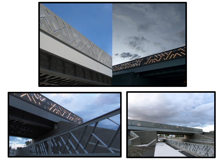
Figure 6
When creating the architectural plan, the designers chose to explore the potential of LED strips to create a strong light signature, making the structure a defining element of the future university campus. They were inspired by the series Wall Drawings by American artist Sol LeWitt and by the work of Krzysztof Wodiczko, a Polish artist whose highly political projections on public buildings brought him international acclaim in the 1980s.
Opposite the MIL Campus, the overpass comes alive at night when four ephemeral paintings evoking the four seasons are projected in alternating sequence onto the railing backdrop. This light choreography is generated by 135 LED bars, which are inserted diagonally in the structure of the railings, behind the perforated metal plates. The LED bars come in two different lengths, some measuring one metre, others 30 cm (see Figure 7).
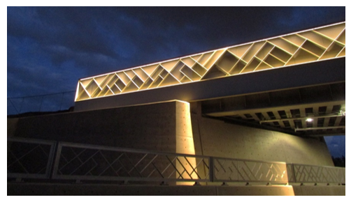
Figure 7
The project, a true visual experience, illustrates how a simple tool can become an urban object evoking the admiration of the public. Using the poetry and subtly of lighting, the designers aimed to mitigate the disruptive impact of a site that has been profoundly altered. In the elements they used, the designers also wished to evoke the long railway history that is currently disappearing from the landscape.
The project of the Université de Montréal’s future Outremont campus goes far beyond the activities of a university. It embraces urban community life by offering a new living space that will serve both the university community and the residents of adjoining neighbourhoods.