
- All
- Bridge Structures
- Building Structures
- Connections
- Fabrication & Erection
- General
- Industrial Structures & Platework
- Seismic & Wind Effects
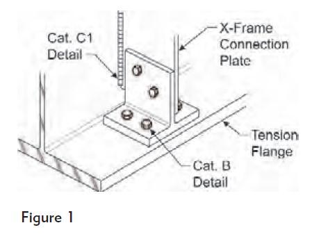
QUESTION: (FALL2010) CSA Standard S6, Canadian Highway Bridge Design Code, requires that cross-frame connection plates be connected to the flanges of bridge girders. The bolted detail, as shown (in Figure 1), appears to be quite popular in rehabilitation work. I heard that this bolted detail qualifies for a “Category B“ fatigue detail, but it is not clear to me how simply bolting the stiffener to the bottom flange makes things better because the web weld is still present.
In order to avoid welded attachments in the tension flange, many older welded steel bridge girders feature cross-frame connection plates that were either cut short from, or ground to bear on, the tension flange. This outdated practice inadvertently resulted in the web taking out-of-plane stresses due to relative displacements of adjacent girders. These stress ranges, typically unaccounted for in the analyses, have been identified as the common cause of distortion-induced fatigue damage to welded bridge girders. Recent editions of CSA S6 require that cross-frames and diaphragms be connected to each flange for a minimum force of 90 kN.
QUESTION: (SPRING2012) When CSA G40.21 300W steel strip is specified as the material for light braces in a building structure, can commercial grade steel products be used instead? What if they are supplied with a test report showing yield stress values matching or exceeding 300 MPa?
ANSWER: No. The reasons include:
a) Commercial grade steel sheet and strip are not produced to meet mandatory mechanical properties, such as minimum yield point, tensile strength and elongation; and
b) Strength levels reported on mill test certificates should not be used as the basis for design. See Clause 5.1.2 of CSA Standard S16-09.
QUESTION: (SPRING2011) In accordance with the National Building Code, steel building systems shall be manufactured by companies certified to CSA A660 “Certification of Manufacturers of Steel Building Systems.” Does this requirement apply to all steel fabricating plants?
ANSWER: No, CSA A660 does not apply to all steel fabricating plants. A steel building system (SBS) features steel for the structural components plus related accessories engineered and designed as a total building system, commonly referred to as “pre-engineered buildings” for which the manufacturer is responsible for both the structural design and fabrication of the building system. Since the designer of the steel building system is also the seller, there is no independent third-party representing the interests of the public. CSA A660 ensures that the SBS manufacturer is complying with the applicable building codes and design standards, and the public is protected.
The vast majority of structural steel fabricators in Canada are only involved with fabrication of building structures that are designed by engineers employed by others. These fabricators are not required to be certified to CSA A660. They are certified to CSA W47.1 (welding). Some are also certified to CISC Quality Certification Program for Steel Structures. For information on CISC Certification Programs, visit the CISC website at http://www.cisc-icca.ca/certification
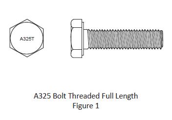
QUESTION: (FALL2015) I recently came across some fully threaded A325 bolts in the connections of a building structure. Are these bolts permitted? Do they have the same resistances versus bolts with regular thread length? How are they identified after installation? Do they offer any benefit?
ANSWER: A325 bolts threaded full length are permitted under Supplementary Requirement S1 of ASTM A325. They are restricted to bolt lengths within the length of four times the nominal diameter.
Bolt resistances: Since the tensile resistance is based on the threaded area (0.75Ab) it is not affected by the longer thread length. However, the bearing-type shear resistance must be reduced to account for threads intercepting the shear plane. When used in a slip-critical joint with a long grip, the smaller (threaded) bolt area in the entire grip affects the relationship between the clamping force and bolt elongation and may result in a reduction in clamping force when using the turn-of-nut installation method. The significance of this effect is a study in pursuit.
Identification: The bolt head is marked with the symbol “A325T” instead of “A325” as shown in Figure 1.
Benefits: They offer no benefit in terms of bolt resistance. However, the fabricator and erector may find their use viable for certain applications from the standpoint of ordering and inventory control, particularly for applications where thin connected steel parts, instead of the bolts, control the connection shear resistance.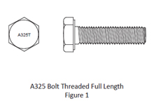
QUESTION: (FALL2015) What is the minimum bolt length requirement for high-strength bolts; must the bolt end past the nut when installed?
ANSWER: A325 and A490 bolts, when installed, must have sufficient thread engagement to develop the tensile strength of the bolt, i.e. they must have the bolt end extending beyond or at least flush with the outer face of the nut.
QUESTION: (SUMMER2015) Are RCSC Specifications mandatory for projects in Canada?
ANSWER: The Research Council on Structural Connections (RCSC) Specification for Structural Joints Using High-Strength Bolts provides state-of-the-art criteria for design and installation of ASTM high-strength bolts and assemblies. These recommendations become mandatory if and when the local code adopts them. In Canada, structural design and inspection of bolted joints and installation of high-strength bolts should comply with CSA Standard S6 or provincial specifications for road bridge structures and S16 for building and other structures to which S16 applies. These standards adopt many recommendations in the RCSC Specification but not all and certainly not all at the same time. In addition, S6 and S16 adopt ASTM specifications for high-strength bolts and bolt assemblies, e.g. ASTM A325 and F1852, by reference. These ASTM Specifications reference other pertinent specifications for testing, etc.
QUESTION: (WINTER2014/2015) The resistances for bolts in tension and shear have increased significantly from those tabulated in the Handbook that I received in 2000. Are the modern high-strength bolts produced to a higher strength or have more recent research and testing substantiated the increase in resistance?
ANSWER: The difference in bolt resistances for the ultimate limit states you noted reflects the increase in the resistance factor for bolts. When the first limit states design standard for design of steel structures, CSA S16.1-74, was introduced in 1974 only two resistance factors were adopted, for simplicity – 0.90 for steel members and 0.67 for welds, bolts, concrete in composite beams and shear connectors. Research studies based on tests and statistic analyses suggest that the resistance factor for high strength bolts can be increased to 0.80, as documented in Guide to Design Criteria for Bolted and Riveted Joints, Second Edition (available via this link: http://boltcouncil.org/files/2ndEditionGuide.pdf.) This increase was first introduced to the Canadian Bridge Design Code when CAN/CSA S6-00 took effect; the change was adopted in S16 when S16-01 was released.
QUESTION: (SUMMER2014) Are bolted moment connections used in a canopy structure required to be slip critical? My question relates to a situation where slip critical connections are not required for deflection control. I have many years of connection design experience but seldom had to provide slip-critical connections for wind-load resisting braced bents or moment frames.
ANSWER: The key question here is whether fatigue is a consideration; will the structure be subjected to repetitive loading and stress reversal? A relatively light canopy type of structure subjected to gusty local wind load may experience stress reversal and a significant number of load cycles to warrant such assessment. The judgement rests with the engineer responsible for the design of the structure. Fatigue design is covered in Clause 26 of S16.
QUESTION: (SPRING2014) Where can I find the standard torque table for pretensioning A325 bolts?
ANSWER: The use of ‘standard torque table’ for pretensioning high strength bolts was discontinued several decades ago. When pretensioning is required, CSA Standard S16 recognizes three bolt installation methods:
a) Turn- of-nut method;
b) Using ASTM F1852 tension control bolt assemblies; and
c) Using an F959 direct tension indicator.Both S16-09 and S16-14 assign a higher slip resistance to bolts installed by the turn-of-nut method versus the other methods for a given Class of contact surface, recognizing the larger pretension typically attained using the turn-of-nut method.
QUESTION: (FALL2013) When ASTM F1852 bolts are used in a simple bearing-type shear connection designed to receive A325 bolts of equal size, does the bolt tension in F1852 bolts due to pre-tensioning reduce the shear strength?
ANSWER: The answer is no. As recognized in CSA S16-09, the bolt in an ASTM F1852 twist-off type bolt assembly has the same ultimate shear strength as an A325 bolt of equal size. The ultimate shear strength of a high strength bolt is not affected by the presence of an initial pretension in the bolt.The Commentary to RCSC Specification for Structural Joints Using High-Strength Bolts offers this explanation:
“When required, pretension is induced in a bolt by imposing a small axial elongation during installation, as described in the Commentary to Section 8. When the joint is subsequently loaded in shear, tension or combined shear and tension, the bolts will undergo significant deformations prior to failure that have the effect of overriding the small axial elongation that was introduced during installation, thereby removing the pretension. Measurements taken in laboratory tests confirm that the pretension that would be sustained if the applied load were removed is essentially zero before the bolt fails in shear (Kulak et al., 1987; pp. 93-94). Thus, the shear and tensile strengths of a bolt are not affected by the presence of an initial pretension in the bolt.”
It should be noted that, for a given Class of faying surface (Class A, B or C), S16-09 assigns a smaller slip resistance to F1852 assemblies versus their A325 counterparts pretensioned by means of the turn-of-nut method, in recognition of the larger pretension typical in the turn-of-nut method of installation.
QUESTION: (SUMMER2013) What are the most common high-strength bolt products used in building construction?
ANSWER: Three-quarter-inch A325 bolts are still very common. Some fabricators/erectors prefer seven-eighth-inch A325 bolts, especially for large projects. A490 bolts are used increasingly in building construction. Typically, they are selected for connections resisting very large forces while A325 bolts may be used elsewhere in the structure. In such applications, care must be taken to prevent A325 bolts from being inadvertently installed in holes designed to receive A490 bolts. It is prudent to segregate them by size, typically, a quarter of an inch difference in diameter.Practical combinations include:
a) 1˝ A490 bolts for heavy connections and ¾˝ A325 bolts elsewhere; and
b) 1⅛˝ A490 bolts for heavy connections and ⅞˝ A325 bolts elsewhere.
Where pre-tensioned installation is required, twist-off type tension-control bolts (assemblies) have emerged to be viable options. ASTM F1852 and ASTM F2280 bolts (twist-off type) share the ultimate-limit-state resistances with A325 bolts and A490 bolts respectively. However, CSA S16-09 specifies smaller values for 5 per cent slip coefficients, c1, for these twist-off type bolt assemblies versus those of high strength bolts pre-tensioned to meet the turn-of-nut method of installation. For further discussion on ASTM F1852 and ASTM F2280, visit Q & A Column in Advantage Steel No. 38. A490 and F2280 products shall not be galvanized.
Use of metric bolts is still rare because they are unavailable unless a special order for a very large quantity is placed with advance notice.
QUESTION: (FALL2012) When designing bolted connections, are seismic loads considered to be static or cyclic?
ANSWER: The Seismic Corner article entitled “Bolted Connections for Seismic Applications” in CISC publication, Advantage Steel No. 31 (Summer 2008), outlined the requirements for bolted connections for seismic applications in accordance with S16-01.The article is available at: https://cisc-icca.ca/ciscwp/product/advantage-steel-no-31/
In NBC 2010 and S16-09, the building height restriction for Conventional Construction where the specified short-period spectral acceleration, IEFaSa(0.2), exceeds 0.35 has been increased. The above mentioned requirements for bolted connections also apply to these taller structures of Conventional Construction.
QUESTION: (SPRING2012) When wide-flange purlins are also subjected to significant axial tension, which is transmitted by connecting the bottom flange to the supports with two transverse lines of high strength bolts, how do I account for shear lag? Specifically, should the effective net area, Ane, be taken as 0.75An, as provided in Clause 12.3.3.2 (c) (ii) of S16-09?
ANSWER: The approach as you described is unconservative. In this situation, the effect of shear lag is more severe than the case for angles connected by one leg with two transverse lines of fasteners. Hence Ane < 0.60An. On the other hand, the lower bound for Ane may be taken as Anf, where Anf is the net area of the connected flange alone. Therefore, Ane should lie somewhere between Anf and 0.60An.
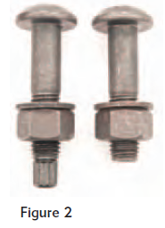
QUESTION: (FALL2010) I have noticed that twist-off bolts are gaining popularity. Are they accepted as high-strength bolts for structural applications? If they are, what are the shear and tensile resistances?
ANSWER: ASTM F1852, twist-off type tension control structural bolt/nut/washer assemblies, are used increasingly in pre-tensioned connections. These bolts feature a splined end which, when properly installed with a special wrench, should shear off when the target pretension is reached (See Figure 2). ASTM F1852 and F2280 bolts have mechanical and chemical properties equivalent to A325 and A490 high-strength bolts, respectively. Specific design requirements can be found in CSA Standard S16-09 Clauses 22.2.5 and 23.8.4 and in Table 3.The tabulated values for ultimate shear resistance in bearing-type connections and tensile resistances of A325 and A490 bolts in Part 3 of the CISC Handbook of Steel Construction may be used for F1852 and F2280 bolts, respectively, whereas smaller values for the 5% slip coefficients, c1, are specified in Table 3 of S16-09 for use of twist-off bolts in slip-critical connections.
Because surface friction is an important factor during installation, these bolt assemblies include hardened washers. Also, the use of tension-control bolts calls for prior testing and particular attention to their handling and storage so as to avoid lubricant deterioration over time.
QUESTION: (SUMMER2014) I am involved with evaluation of an existing building structure for compliance with the current code. The structure is in a sound condition. It satisfies the building code and CSA S16-09 for the intended occupancy except that the column bases have 2 anchor rods instead of 4. In one area, a row of small wide-flange columns sit on a concrete wall. The x-axis of these columns, their anchor rods and the centre line of the wall all lie in the same plane. It is impossible to install 4 anchor rods in the normal configuration to this relatively thin wall. However, I can provide 4 collinear rods per column by adding 2 more. Is this collinear pattern acceptable?
ANSWER: I see two parts in your question:
a) Is collinear distribution of 4 anchor rods in compliance with Clause 25.2 of S16? The requirement for a minimum of 4 anchor rods aims to ensure erection safety. The rods should be positioned to provide an adequate lever arm against overturning in more than one direction. Clause 25.2 of S16-14 specifies 4 non-collinear rods per column, unless special precautions are taken.
b) Does Clause 25.2 apply to a structure that has been completed and in service? No, it is an erection safety requirement.
QUESTION: (FALL2013) When anchor bolts are used to transfer lateral shear in a column base, what is the maximum hole size permitted? I have come across a guide in the literature recommending a maximum hole diameter of 1/16” larger than the anchor bolt diameter but the contractors demand much larger holes.
ANSWER: Typically, a shear lug(s) is used to transfer large shear forces between a column base and the footing. Anchor rods are also used, generally to transfer smaller shear. Use of standard hole size for bolts, or 1/16” hole clearance, is not a practical solution as larger holes are necessary in order to accommodate anchor rod installation tolerances, etc. In that case, appropriately designed washers with standard holes are field-welded to the base plate in the erected position to transfer the shear forces. It has been reported in research studies that these anchor rods are subjected to bending as well as shear and any tension where present.
QUESTION: (SUMMER2013) Is there a standard for anchor bolts?
ANSWER: Yes, ASTM F1554 covers three grades of anchor bolts: Grade 36 (248 MPa), Grade 55 (380 MPa) and Grade 105 (724 MPa).The vast majority of anchor bolts (or anchor rods as defined in CSA S16-09) are used to position, level and secure base plates for concentrically loaded gravity columns. Fabricators have traditionally supplied these anchor rods manufactured from round bar stocks produced to ASTM A36 (or CSA G40.21 300W). Since the introduction of ASTM F1554, Grade 36 products fill this role.Grades 55 and 105 are produced to meet higher specified strengths. In addition, when specified in the purchased order as a ‘supplementary requirement,’ they are supplied to meet specific Charpy notch-toughness with test values.
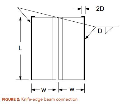
QUESTION: (2015) For a knife-edge beam shear connection with double-angle welded to the support (Figure 2), can the top edge of the angles also be welded in order to increase the weld capacity?
QUESTION: (FALL2015) I recently came across some fully threaded A325 bolts in the connections of a building structure. Are these bolts permitted? Do they have the same resistances versus bolts with regular thread length? How are they identified after installation? Do they offer any benefit?
QUESTION: (WINTER2014/2015) How is the shear resistance for gross section of gusset plates determined – should I use Clause 13.4.3 of S16-09 on webs of flexural members not having two flanges or Clause 13.11 on block shear? They give very different results.
ANSWER: Neither. Clause 21.12, “Connected elements under combined tension and shear stresses”, a new clause introduced in CSA S16-14, covers this.
QUESTION: (SUMMER2014) Are bolted moment connections used in a canopy structure required to be slip critical? My question relates to a situation where slip critical connections are not required for deflection control. I have many years of connection design experience but seldom had to provide slip-critical connections for wind-load resisting braced bents or moment frames.
ANSWER: The key question here is whether fatigue is a consideration; will the structure be subjected to repetitive loading and stress reversal? A relatively light canopy type of structure subjected to gusty local wind load may experience stress reversal and a significant number of load cycles to warrant such assessment. The judgement rests with the engineer responsible for the design of the structure. Fatigue design is covered in Clause 26 of S16.
QUESTION: I find the design requirements for pin-connected tension members as stipulated in CSA S16-09 very difficult to satisfy. They appear to mandate the use of eyebars. Have I missed something?
ANSWER: The requirements in CSA S16-09 aim to ensure a gross-section yielding ultimate limit state and are therefore quite restrictive. New requirements have been introduced in CSA S16-14. This new provision improves design versatility considerably.
QUESTION: (SPRING2014) When only one leg of an angle tension member is attached to its end supports, with longitudinal fillet welds, how do I determine if shear lag is important and how is it accounted for?
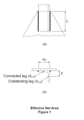
ANSWER: The effect due to shear lag in a tension member is usually accounted for by means of an effective area method. For weld-connected members, Clause 12.3.3.3 of CSA S16-09 applies to members of various cross sections in general. The cross-section area of the angle is divided into two components, i.e., the attached leg and the outstanding leg. Figure 1(a) shows an angle connected by a pair of longitudinal welds of length, L. For the attached leg, shear lag is a factor when L ≤ 2w2. In accordance with Clause 12.3.3.3 (b)(ii) and (iii), its effective net area, An2, as shown in Figure 1(b), is determined based on the weld configuration and, for short welds, also the leg thickness. The effective net area of the outstanding leg, An3, is calculated according to Clause 12.3.3.3(c). Its shear lag effect is given as a function of the ratio of the eccentricity of the weld with respect to the centroid of the outstanding leg, x, to the weld length, L. Then the tensile resistance of the member is calculated in accordance with Clause 13.2(a)(iii) using the total effective net area of the angle section, Ane = An2 + An3.
Further information may be found in the CISC Commentary on CSA S16-09 in Part 2 of the Handbook of Steel Construction.
QUESTION: (SPRING2013) Clause 13.11 of S16-09 appears to have omitted the check for shear rupture of net section. What has happened to the shear rupture failure mode and where is the provision for pure shear rupture?
ANSWER: The equation provided in Clause 13.11 of S16-09, as shown below, consists of both the tension and shear contributions to the block shear resistance of a bolted joint.
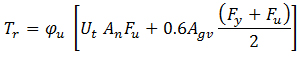
The first term accounts for the resistance against tension whereas the second term represents the shear component. An example is shown in Figure 2a. The ultimate resistance of block shear is attained when the net section(s) subjected to tension reaches its fracture capacity. Typically, the deformation associated with this tensile capacity is too small to mobilize complete shear rupture at the same time. As recommended by Driver et al, the shear component is based on 0.6 times the mean value of Fy and Fu in this calculation. It should be noted that the gross area in shear, Agv(taken as the area of the plane(s) tangential to the bolt holes), is used in this calculation.Pure shear rupture, as shown for the example in Figure 2b, should also be considered. The second term of the equation above covers it. In the absence of the above-mentioned deformation incompatibility, larger shear resistance can be attained for pure shear rupture. However, Clause 13.11 provides a simple solution.
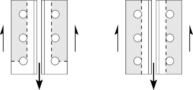
Figure 2a: Block Shear Figure 2b: Shear Rupture
QUESTION: (SPRING2013) How is the strength reduction factor for multi-orientation fillet welds, Mw, applied? Please show an example.
ANSWER: In the weld configuration shown in Figure 1, 8-millimetre fillet welds are used, Xu = 490 MPa and the plate is G40.21 350W steel. Note that the farside plate is thicker.
In accordance with CSA S16-09 Clause 13.13.2.2:
Vr = 0.67 ɸw Aw Xu (1.00 + 0.50 sin1.5 θ) Mw
where:θ = angle of axis of weld segment with respect to the line of action of the applied force
Mw = strength reduction factor for multi-orientation fillet welds
a) Weld segment at θ = 60o:
Orientation of the weld segment under consideration: θ1 = 60o
Orientation of the weld segment in the joint that is nearest to 90o: θ2 = θ1 = 60o
![]()
Orientation of the weld segment in the joint that is nearest to 90o: θ2 = 60o
Vr = 2 x 0.67 x 0.67 x 8 x 100 x 0.707 x 0.490 (1.00 + 0.50 sin1.5 0o) 0.895
+ 0.67 x 0.67 x 8 x 120 x 0.707 x 0.490 (1.00 + 0.50 sin1.5 60o) 1.00
= 2 x 111 + 209 = 431 kNFor matching electrodes, the base metal resistance need not be checked
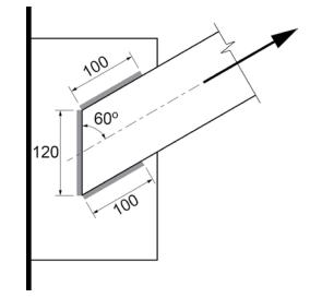
Figure 1: Strength Reduction for Multi-Orientation Fillet Welds
QUESTION: (FALL2012) When designing bolted connections, are seismic loads considered to be static or cyclic?
ANSWER: The Seismic Corner article entitled “Bolted Connections for Seismic Applications” in CISC publication, Advantage Steel No. 31 (Summer 2008), outlined the requirements for bolted connections for seismic applications in accordance with S16-01. The article is available at: https://cisc-icca.ca/ciscwp/product/advantage-steel-no-31/
In NBC 2010 and S16-09, the building height restriction for Conventional Construction where the specified short-period spectral acceleration, IEFaSa(0.2), exceeds 0.35 has been increased. The above mentioned requirements for bolted connections also apply to these taller structures of Conventional Construction.
QUESTION: (FALL2012) When designing fillet welds in shear, is it necessary to check the base metal resistance at the fusion face?
ANSWER: In accordance with S16-01, the shear resistance of fillet welds is taken as the lesser of: (a) the weld metal resistance given as a function of the ultimate strength of the electrode, Xu , and the effective throat area, Aw and (b) the base metal resistance given as a function of its tensile strength, Fu , and the fusion face area, Am. Unless over-matched electrodes are used the base metal resistance does not govern the design of longitudinally loaded joints. However, when the weld orientation approaches the transversely loaded case the base metal resistance governs due to the significantly larger weld metal resistance.In S16-09, it is no longer necessary to check the base metal strength at the fusion face when matching electrodes are used (Clause 13.13.2.2). Research studies conducted at the University of Alberta have demonstrated that the base metal resistance determined using the virgin strength of the base metal does not represent the shear resistance. The researchers pointed to the fact that the properties of the base metal at the fusion face are influenced by intermixing of the weld and base metals. Unless over-matched electrodes are used, base metal resistance at the fusion face need not be checked, regardless of weld orientation.For a list of matching electrodes for CSA G40.21 steels, see Table 4 in S16-09.
QUESTION: (SPRING2012) When wide-flange purlins are also subjected to significant axial tension, which is transmitted by connecting the bottom flange to the supports with two transverse lines of high strength bolts, how do I account for shear lag? Specifically, should the effective net area, Ane, be taken as 0.75An, as provided in Clause 12.3.3.2 (c) (ii) of S16-09?
ANSWER: The approach as you described is unconservative. In this situation, the effect of shear lag is more severe than the case for angles connected by one leg with two transverse lines of fasteners. Hence Ane < 0.60An. On the other hand, the lower bound for Ane may be taken as Anf, where Anf is the net area of the connected flange alone. Therefore, Ane should lie somewhere between Anf and 0.60An.
QUESTION: (SPRING2011) Is knife edge angle connection the right choice for axial tension or combined shear and axial tension?
ANSWER: Knife edge angle connection, commonly known as knife connection, is a very common type of beam shear connection. It features a pair of angles that are typically welded to the column in the shop and bolted to the beam web in the field (Figure 1). While knife connection serves as a popular beam shear connection, its use is not recommended where significant axial tensile forces are to be transmitted, such as end connections for braced frame members and collectors that are subjected to significant axial tensile forces. Research studies, reported in the reference below, have demonstrated that knife connection exhibits limited axial tensile resistance. In the reference below, the test results of several other common beam shear connections subjected to combined shear and axial forces were also reported.
Reference: Guravich, S. J. and Dawe, J. L. 2006. Simple beam connections in combined shear and tension. Canadian Journal of Civil Engineering. 33(4): 357-372.
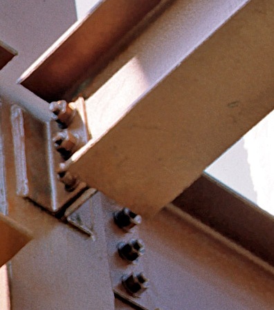
Figure 1: Knife Edge Connection
QUESTION: (2015) Clause 13.13.2.2 of S16-14 waives the base metal capacity requirement for fillet welds except where over-matched electrodes are used. This suggests that the rated strength of the over-matched electrode should be used to calculate the weld resistance but W59-13 requires that matching electrode strength to be used in this situation. What should I do?
ANSWER: Until these standards reconcile, they can be satisfied if the matching electrode strength (smaller) is used in this situation.
QUESTION: (SPRING2013) How is the strength reduction factor for multi-orientation fillet welds, Mw, applied? Please show an example.
ANSWER: In the weld configuration shown in Figure 1, 8-millimetre fillet welds are used, Xu = 490 MPa and the plate is G40.21 350W steel. Note that the farside plate is thicker.
In accordance with CSA S16-09 Clause 13.13.2.2:
Vr = 0.67 ɸw Aw Xu (1.00 + 0.50 sin1.5 θ) Mw
where:θ = angle of axis of weld segment with respect to the line of action of the applied force
Mw = strength reduction factor for multi-orientation fillet welds
a) Weld segment at θ = 60o:
Orientation of the weld segment under consideration: θ1 = 60o
Orientation of the weld segment in the joint that is nearest to 90o: θ2 = θ1 = 60o
![]()
Orientation of the weld segment in the joint that is nearest to 90o: θ2 = 60o
Vr = 2 x 0.67 x 0.67 x 8 x 100 x 0.707 x 0.490 (1.00 + 0.50 sin1.5 0o) 0.895
+ 0.67 x 0.67 x 8 x 120 x 0.707 x 0.490 (1.00 + 0.50 sin1.5 60o) 1.00
= 2 x 111 + 209 = 431 kNFor matching electrodes, the base metal resistance need not be checked
Figure 1: Strength Reduction for Multi-Orientation Fillet Welds
QUESTION: (FALL2012) When designing fillet welds in shear, is it necessary to check the base metal resistance at the fusion face?
ANSWER: In accordance with S16-01, the shear resistance of fillet welds is taken as the lesser of: (a) the weld metal resistance given as a function of the ultimate strength of the electrode, Xu , and the effective throat area, Aw and (b) the base metal resistance given as a function of its tensile strength, Fu , and the fusion face area, Am. Unless over-matched electrodes are used the base metal resistance does not govern the design of longitudinally loaded joints. However, when the weld orientation approaches the transversely loaded case the base metal resistance governs due to the significantly larger weld metal resistance.
In S16-09, it is no longer necessary to check the base metal strength at the fusion face when matching electrodes are used (Clause 13.13.2.2). Research studies conducted at the University of Alberta have demonstrated that the base metal resistance determined using the virgin strength of the base metal does not represent the shear resistance. The researchers pointed to the fact that the properties of the base metal at the fusion face are influenced by intermixing of the weld and base metals. Unless over-matched electrodes are used, base metal resistance at the fusion face need not be checked, regardless of weld orientation.For a list of matching electrodes for CSA G40.21 steels, see Table 4 in S16-09.
QUESTION: (SUMMER2014) I am involved with evaluation of an existing building structure for compliance with the current code. The structure is in a sound condition. It satisfies the building code and CSA S16-09 for the intended occupancy except that the column bases have 2 anchor rods instead of 4. In one area, a row of small wide-flange columns sit on a concrete wall. The x-axis of these columns, their anchor rods and the centre line of the wall all lie in the same plane. It is impossible to install 4 anchor rods in the normal configuration to this relatively thin wall. However, I can provide 4 collinear rods per column by adding 2 more. Is this collinear pattern acceptable?
ANSWER: I see two parts in your question:
a) Is collinear distribution of 4 anchor rods in compliance with Clause 25.2 of S16? The requirement for a minimum of 4 anchor rods aims to ensure erection safety. The rods should be positioned to provide an adequate lever arm against overturning in more than one direction. Clause 25.2 of S16-14 specifies 4 non-collinear rods per column, unless special precautions are taken.
b) Does Clause 25.2 apply to a structure that has been completed and in service? No, it is an erection safety requirement.
QUESTION: (FALL2015) I am involved with the design of an unenclosed industrial structure for which neither the building code nor the bridge code applies. Should I specify notch-tough steel? Are notch-tough W-shapes available? How do I determine the appropriate level of notch-toughness?
ANSWER: Brittle fracture is a complex subject. In order to limit the probability of its occurrence to an acceptable level, one should account for the consequence of failure together with many influential factors as described in Annex L of CSA S16-14. Notch toughness of steel is only one of these factors. Often, fracture control for structures other than buildings and bridges involves identifying the safe options then choosing the most viable solution. Hence the engineer(s) who is responsible for the design, construction specifications and supervision, QA, QC, recommendation for future inspections, etc. is in the best position to make this decision.
With respect to steel grades and their availability, this is the current situation. Although common structural steels, such as CSA G40.21 Types W and A steels generally possess notch toughness that is superior to many steel products used for non-structural applications, they are not produced to meet specific impact testing requirements. Types WT and AT steels are. Purchasers of Types WT and AT steels must also specify the required notch-toughness category that establishes the Charpy V-notch test temperature and energy level. Similarly, purchasers of ASTM steel grades, such as A992, must specify the appropriate test temperature and energy level if they so desire. To our knowledge, a North American mill produces W-sections up to about 440 kg/m to notch-toughness requirements comparable to CSA 350WT Cat. 3. It should be noted that Charpy V-notch test requirements add cost and lead time. Therefore, they should not be specified indiscriminately.QUESTION: (FALL2010) CISC/CPMA Standard 1-73a versus CISC/CPMA Standard 2-75: What do they have in common and what are the major differences?
QUESTION: (SUMMER2016) In National Building Code of Canada 2015, the period dependant Site Coefficient F(T), used for determination of seismic Design Spectral Accelerations, has replaced Site Coefficients Fa and Fv. CSA Standard S16-14, however, continues to reference Site Coefficients, Fa and Fv. Is S16-14 out of step with NBC 2015?
ANSWER: CSA S16-14 is compatible with NBC 2015. In S16-14, coefficients Fa and Fv, appear in two expressions: the short-period specified spectral acceleration ratio, IEFaSa(0.2), and the one-second specified spectral acceleration ratio, IEFvSa(1.0). Certain values of these quantities serve as triggers for more stringent requirements whereas other values set the conditions for relaxation. Although F(T) has replaced Fa and Fv for the purpose of determination of Design Spectral Accelerations in NBC 2015 the Code retains the expressions IEFaSa(0.2) and IEFvSa(1.0) as triggers. As defined in Sentence 4.1.8.4. (7) of NBC 2015, Fa = F(0.2) and Fv = F(1.0). Ideally, F(0.2) and F(1.0) should also replace Fa and Fv respectively in these trigger expressions. This was not possible in the 2015 code cycle for the following reason: In order to be considered for adoption by NBC 2015, CSA material design standards, S16, A23.3 etc., must be published in 2014. However, changes proposed for NBC, including the period dependant Site Coefficient F(T), could not be finalized in time to meet the publication schedule for the CSA standards.
QUESTION: (SUMMER2013) Is there a standard for anchor bolts?
ANSWER: Yes, ASTM F1554 covers three grades of anchor bolts: Grade 36 (248 MPa), Grade 55 (380 MPa) and Grade 105 (724 MPa).
The vast majority of anchor bolts (or anchor rods as defined in CSA S16-09) are used to position, level and secure base plates for concentrically loaded gravity columns. Fabricators have traditionally supplied these anchor rods manufactured from round bar stocks produced to ASTM A36 (or CSA G40.21 300W). Since the introduction of ASTM F1554, Grade 36 products fill this role.
Grades 55 and 105 are produced to meet higher specified strengths. In addition, when specified in the purchased order as a ‘supplementary requirement,’ they are supplied to meet specific Charpy notch-toughness with test values.
QUESTION: (SUMMER2013) What are the most common high-strength bolt products used in building construction?
ANSWER: Three-quarter-inch A325 bolts are still very common. Some fabricators/erectors prefer seven-eighth-inch A325 bolts, especially for large projects. A490 bolts are used increasingly in building construction. Typically, they are selected for connections resisting very large forces while A325 bolts may be used elsewhere in the structure. In such applications, care must be taken to prevent A325 bolts from being inadvertently installed in holes designed to receive A490 bolts. It is prudent to segregate them by size, typically, a quarter of an inch difference in diameter.
Practical combinations include:
a) 1˝ A490 bolts for heavy connections and ¾˝ A325 bolts elsewhere; and
b) 1⅛˝ A490 bolts for heavy connections and ⅞˝ A325 bolts elsewhere. Where pre-tensioned installation is required, twist-off type tension-control bolts (assemblies) have emerged to be viable options. ASTM F1852 and ASTM F2280 bolts (twist-off type) share the ultimate-limit-state resistances with A325 bolts and A490 bolts respectively. However, CSA S16-09 specifies smaller values for 5 per cent slip coefficients, c1, for these twist-off type bolt assemblies versus those of high strength bolts pre-tensioned to meet the turn-of-nut method of installation. For further discussion on ASTM F1852 and ASTM F2280, visit Q & A Column in Advantage Steel No. 38.
A490 and F2280 products shall not be galvanized. Use of metric bolts is still rare because they are unavailable unless a special order for a very large quantity is placed with advance notice.
QUESTION: (FALL2010) CISC/CPMA Standard 1-73a versus CISC/CPMA Standard 2-75: What do they have in common and what are the major differences?
ANSWER: These standards provide essentially the same laboratory requirements. The provision for surface preparation reflects the key difference. In addition to removal of grease and oil in accordance with SSPC Standard SP1, CISC/CPMA 2-75 requires steel cleaning in accordance with SSPC SP7, Brush-Off Blast Cleaning. Where CISC/CPMA 2-75 serves as a primer, it should be compatible with the top coat. CISC/CPMA 1-73a is a standard for one-coat paint, not a standard for primer.
QUESTION: (SPRING2011) Should I aim for full composite action for composite beams in building structures? Otherwise, where do I begin?
ANSWER: Due to the substantial increase in bending resistance gained from composite action, partial composite capacity for beams usually suffices. Factors other than the ultimate limit states of the composite beam often dictate the steel beam size and the percentage of composite shear connection:
- In order to benefit from one of the advantages of steel construction, beams are unshored. In that case, construction loading conditions may govern;
- Since the deck flutes typically run perpendicular to the beam, as shown in Figure 2, (and wide-rib profile deck should be used for optimal stud shear capacity) full composite design often results in placing multiple studs per flute resulting in inefficient use of shear studs due to overlap of concrete shear cones; and
- Live load deflection or floor vibration control may govern the design.
In accordance with S16-09, 40% or larger composite shear connection must be provided for composite resistance. Due to the above-mentioned factors, most composite beams are designed for 40% to 60% shear connection. However, composite girders are usually connected for higher composite capacity because the deck flutes run parallel to the girder and, during construction, the girder is often laterally braced by the beams framing into it (Figure 3). Where composite action is only required for stiffness measures, S16 permits 25% shear connection as the minimum.
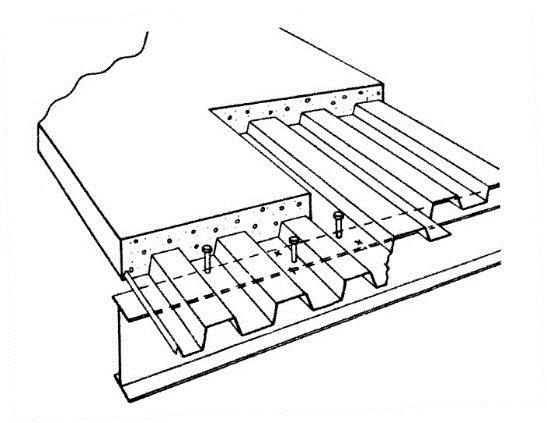
Figure 2: Deck Perpendicular to Beam
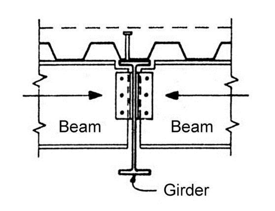
Figure 3: Deck Parallel to Girder
QUESTION: (SUMMER2015) As stated in the Commentary to S16-09, the slenderness expressions provided in Clause 13.3.3 for ‘Single-Angle Members in Compression’ are not intended for use in the design of braces in braced frames. I want to use equal-leg compression braces in a braced frame. How are these single-angle braces designed?
ANSWER: When single-angle braces are used, they typically serve as tension-only braces due to their limited compression resistance. If they must resist significant compression with only one leg connected, they must be designed as eccentrically loaded columns. In this case, Clause 13.3.2 covers flexural and flexural-torsional buckling resistances and Clause 13.8.3 addresses combined axial compression and bending.
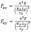
QUESTION: (FALL2013) When checking flexural buckling of a channel section under axial load, what radius of gyration should be used to calculate Fex and Fey?
Answer: In S16-09 Clause 13.3.2, the elastic buckling stresses are given by:
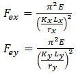
For singly-symmetric sections such as channels, the same clause specifies that the y-axis is taken as the axis of symmetry. But when using the tables of properties and dimensions for channels in Part 6 of the Handbook of Steel Construction, the x-axis is defined as the axis of symmetry. Therefore, Fex should be calculated using the radius of gyration ry as given in the Handbook tables, and likewise Fey should be calculated using rx.
QUESTION: (SPRING2012) There was once a traditional steel design provision that permitted moment resisting frames to be proportioned for lateral loads independent of gravity loads. Is this empirical method recognized by S16 Standard today?
ANSWER: No. Since the introduction of CSA Standard S16-01, all concurrent loads as specified in S16 and NBC load combinations must be considered to act simultaneously (except when a variable load counteracts the effect of the principal load then the variable load should be excluded in that load combination).
QUESTION: (PRINTEMPS2011) Conformément au Code national du bâtiment, les systèmes de bâtiment en acier devront être fabriqués par des entreprises possédant la certification CSA A660 « Certification des fabricants de systèmes de bâtiment en acier ». Cette exigence s’applique-t-elle à tous les fabricants d’acier?ng plants?
RÉPONSE: Non, la norme CSA A660 ne s’applique pas à tous les fabricants d’acier. Un système de bâtiment d’acier comporte de l’acier pour les éléments de charpente ainsi que des accessoires conçus et fabriqués pour produire un système de bâtiment total, qu’on appelle souvent « bâtiment métallique préfabriqué » et pour lequel le fabricant est responsable aussi bien de la conception structurale que de la fabrication du système de bâtiment. Puisque le concepteur du système de bâtiment en acier est également le vendeur, il n’y a pas de tierce partie indépendante représentant les intérêts du public. La norme CSA A660 vise à s’assurer que le fabricant de systèmes de bâtiment en acier se conforme au code du bâtiment et aux normes de conception applicables, et que le public est protégé. La grande majorité des fabricants d’acier de charpente canadiens fabriquent des structures de bâtiments qui sont conçues par des ingénieurs employés par d’autres. Ces fabricants ne sont pas tenus d’obtenir la certification CSA A660. En revanche, ils sont certifiés CSA W47.1 « Certification des compagnies de soudage par fusion de l’acier ». Certains possèdent aussi la Certification qualité de l’ICCA pour la fabrication de l’acier.
Pour plus d’information, visitez :http://www.cisc-icca.ca/certification.
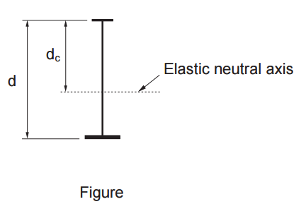
QUESTION: (SUMMER2016) I am proportioning a mono-symmetric I-girder whose web-slenderness, h/w, marginally satisfies the Class 3 limit for W-shapes in pure bending in accordance with Table 2 of S16-09. Does this limit apply to mono-symmetric sections?
ANSWER: No, the limits for I-sections are provided in Table 2 of S16-09 for sections with equal flanges. CSA Standard S6, Canadian Highway Bridge Design Code, in Clause 10.10.3.1, addresses Class 3 web-limits for mono-symmetric I-sections. In this clause, the value of h is replaced by 2dc, where dc is the distance from the neutral axis to the compressive extreme fibre (see Figure).
QUESTION: (2014) I am calculating the laterally unsupported bending resistance of a singly symmetric I-section having flanges of unequal thickness. What should be the value of t in the expressions for βx and Cw provided in Sub-clause 13.6 (e) of S16-09?
ANSWER: In both expressions, the value for ʽd-tʼ may be taken as the centroidal distance between the flanges. Cw may also be calculated using the formula given under Built-up Sections in Part 6 of CISC Handbook of Steel Construction.
QUESTION: (FALL2012) How do I determine the elastic bending resistance of a cantilever plate subject to lateral-torsional buckling?
ANSWER: For a fix-ended plate subject to bending about its strong axis but laterally unbraced, the Guide to Stability Design Criteria for Metal Structures, 6th Edition (R.D. Ziemian, John Wiley & Sons, 2010) gives expressions for the elastic buckling moment (Mu), depending on the height of load application. For example, when subjected to a point load at its tip (see Figure):
a) For top surface loading:
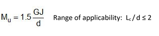
where E and G are the elastic and shear modulii respectively, Iy is the minor-axis moment of inertia, J the St. Venant torsional constant, “d” the plate depth, and Lc the cantilever length.
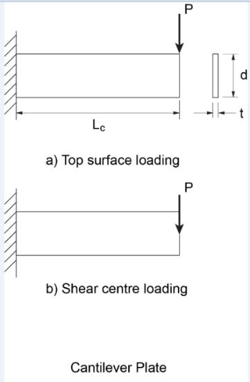 NOTE: In Advantage Steel #44, this column referenced the expressions for the elastic lateral-torsional buckling moment of cantilevers provided in the Guide to Stability Design Criteria for Metal Structures, 6th Edition. In comparison with recent studies using finite element analyses, the expression “Mc = 1.5GJ/d” gives unconservative values for plates (rectangular section) and long cantilevers of I-sections prone to lateral-torsional buckling. It should not be used for plate cantilevers significantly longer than twice their depth.
QUESTION: (SUMMER2012) In the design of continuous beams and Gerber beams can I assume the inflection points are laterally braced against lateral-torsional buckling?
ANSWER: One must not confuse the inflection points in the vertical bending moment diagram with the inflection points in the laterally buckled shape. In general, the buckled shape is not known at the design stage. Since the inflection points in the bending moment diagram generally do not coincide with those of the buckled shape they should not be taken as laterally braced unless they are braced.
QUESTION: (WINTER2014/2015) How is the shear resistance for gross section of gusset plates determined – should I use Clause 13.4.3 of S16-09 on webs of flexural members not having two flanges or Clause 13.11 on block shear? They give very different results
ANSWER: Neither. Clause 21.12, “Connected elements under combined tension and shear stresses”, a new clause introduced in CSA S16-14, covers this.
QUESTION: (SUMMER2014) I find the design requirements for pin-connected tension members as stipulated in CSA S16-09 very difficult to satisfy. They appear to mandate the use of eyebars. Have I missed something?
QUESTION: (SPRING2014) When only one leg of an angle tension member is attached to its end supports, with longitudinal fillet welds, how do I determine if shear lag is important and how is it accounted for?

QUESTION: (SPRING2011) Is knife edge angle connection the right choice for axial tension or combined shear and axial tension?
Figure 1: Knife Edge Connection
QUESTION: (SUMMER2015) How are the torsional constants calculated for open sections in the CISC Handbook? Using general strength of material formulas, I can reproduce the values for angles, but I obtain different values for other shapes.
ANSWER: Torsional section properties found in the Handbook include the St. Venant constant (J) and the warping constant (Cw). General formulas do not usually incorporate the contributions of the round fillets at the intersection of the web and flange(s) in open sections, as shown in Figure 1. The fillets are not taken into account for angle sections, but they are included for other open sections such as wide flange and Tee shapes.
While the warping constant is not significantly affected by the fillets, the St. Venant constant is significantly increased, and calculations in the Handbook are based on the following reference: El Darwish, I.A. and Johnston, B.G. 1965. Torsion of Structural Shapes. ASCE Journal of the Structural Division, Vol. 91, ST1. (Errata: ASCE Journal of the Structural Division, Vol. 92, ST1, 1966)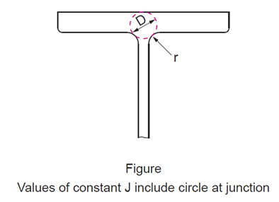
QUESTION: (WINTER2014/2015) What is the correct fatigue ‘Detail Category’ for a coped beam detail? S16-14 shows Category E1 whereas W59-13 and S16-09 show Category B
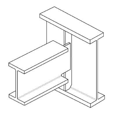
Figure: Beam with a Cope Detail
QUESTION: (SUMMER2014) Are bolted moment connections used in a canopy structure required to be slip critical? My question relates to a situation where slip critical connections are not required for deflection control. I have many years of connection design experience but seldom had to provide slip-critical connections for wind-load resisting braced bents or moment frames.
QUESTION: (FALL2010) CSA Standard S6, Canadian Highway Bridge Design Code, requires that cross-frame connection plates be connected to the flanges of bridge girders. The bolted detail, as shown (in Figure 1), appears to be quite popular in rehabilitation work. I heard that this bolted detail qualifies for a “Category B“ fatigue detail, but it is not clear to me how simply bolting the stiffener to the bottom flange makes things better because the web weld is still present.
ANSWER:Where the stiffener also serves as a cross-frame connection plate, both distortion-induced fatigue and load-induced fatigue should be considered. The bolted detail as shown does not alter the stiffener-to-web welded fatigue detail with respect to load-induced fatigue because this welded detail remains “Category C1”. However, connecting the connection plate to the flanges (when done correctly) should improve the distortion-induced fatigue resistance substantially.
In order to avoid welded attachments in the tension flange, many older welded steel bridge girders feature cross-frame connection plates that were either cut short from, or ground to bear on, the tension flange. This outdated practice inadvertently resulted in the web taking out-of-plane stresses due to relative displacements of adjacent girders. These stress ranges, typically unaccounted for in the analyses, have been identified as the common cause of distortion-induced fatigue damage to welded bridge girders. Recent editions of CSA S6 require that cross-frames and diaphragms be connected to each flange for a minimum force of 90 kN.
QUESTION: (2014) What are the key characteristics of ASTM A1085 HSS as compared to A500 Grade C and CSA G40.20/21 products?
ANSWER: In a nutshell, ASTM A1085 HSS are produced to meet requirements comparable to those of CSA G40.20/21 350WT Category 1. The material is required to conform to a minimum average Charpy V-notch impact value of 25 ft-lb at 40°F (approximately 34 J at 4°C), as represented by the test specimen. In addition, a maximum yield stress at 70 ksi (approximately 485 MPa) as well as a minimum yield stress at 50 ksi (345 MPa) apply. Minimum corner radius control is another measure unique to A1085 square and rectangular HSS. All in all, A1085 HSS are superior to A500 products in various aspects.
QUESTION: (2014) What sectional properties may I use for the design of ASTM A1085 HSS?
ANSWER: Wall-thickness and mass tolerances for ASTM A1085 products are essentially the same as those specified for HSS in CSA G40.20-13. Hence sectional properties provided for CSA G40.20 HSS in the CISC Handbook of Steel Construction, which are calculated from nominal wall thickness, depth, width and diameter, may be used for design. Since A1085 is a new standard, it is not included in Clause 5.1.3 of S16-09; until it is covered, use of A1085 may require Approval in accordance with Clause 5.1.1.
QUESTION: (2014) How do I determine the factored axial compressive resistance of an ASTM A1085 HSS column?
ANSWER: Since the manufacturing method for A1085 HSS is also permitted for the manufacturing of Class C CSA G40.20 HSS, the factored axial compressive resistance of an A1085 HSS column may be determined in accordance with Clause 13.3.1 with the value of n taken as 1.34. The factored axial compressive resistance tables for Class C G40.20 HSS Columns in the CISC Handbook of Steel Construction may be used provided an adjustment for the small difference in Fy values (345 MPa vs. 350 MPa) is accounted for. Purchasers of A1085 HSS may specify heat treatment, as a Supplemental Requirement S1, which also conforms to the stress-relieve requirement for Class H G40.20 HSS. Hence an n-value of 2.24 may be used for A1085 HSS supplied with Supplemental Requirement S1.
However, use of notch-tough steel as gravity columns is an exception.
QUESTION: (2014) Are ASTM A1085 products readily available?
ANSWER: ASTM A1085 is a new standard, introduced in 2013. Atlas Tube Canada ULC has started taking orders in 2013. Time will tell if they will be readily available from service centres.
QUESTION: (SUMMER2011) What are the major differences between Welded Wide Flange sections and welded I-girders?
ANSWER: Limitations for WWF shapes versus welded I-girders
- WWF shapes are restricted to a maximum depth of 2,000 mm.
- WWF shapes are standardized sections, whereas plate girder cross-sectional dimensions may vary.
- WWF shapes are straight members.
- WWF shapes have a limit on built-in camber (though they can be quite versatile).
- The web-to-flange weld strength of WWF shapes is limited to the capacity of a 20 mm web.
- A cross-section change involves splicing 2 WWF sections, whereas a plate girder cross-section change may involve changing the size of 1, 2 or 3 plates.
- Butt-welded splices are permitted in WWF production; when fatigue is a design consideration the production splice details must be accounted for.
Dimensional tolerances:WWF shapes are supplied to the requirements of CSA G40.20, whereas welded shapes should comply with W59 requirements. These standards share essentially identical tolerance requirements for length, camber, web flatness, combined warpage and tilt and lateral deviation between centreline of web and centreline of flange at contact surface. The under-tolerances for section depth are also identical. W59 has no provision for flange width tolerances, but G40.20 does. It should also be noted that tension testing of the web-to-flange welds is part of the WWF production requirements.
QUESTION: (SUMMER2016) I am proportioning a mono-symmetric I-girder whose web-slenderness, h/w, marginally satisfies the Class 3 limit for W-shapes in pure bending in accordance with Table 2 of S16-09. Does this limit apply to mono-symmetric sections?
ANSWER: No, the limits for I-sections are provided in Table 2 of S16-09 for sections with equal flanges. CSA Standard S6, Canadian Highway Bridge Design Code, in Clause 10.10.3.1, addresses Class 3 web-limits for mono-symmetric I-sections. In this clause, the value of h is replaced by 2dc, where dc is the distance from the neutral axis to the compressive extreme fibre (see Figure).
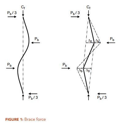
QUESTION: (2015) When using the direct method in accordance with Clause 9.2.6.2 of CSA S16-14, I was surprised to find that, for a given column force, Cf, the bracing force, Pb, increases as the number of braces is increased from 1 to 2. Does this make sense?
ANSWER: Intuitively, it would seem that adding braces to stabilize a compression member should reduce the brace force per brace, as there are more braces to “share” the stabilizing forces. But in fact, the opposite is true. It should be noted that the brace forces in two adjacent braces do not act in the same direction but the opposite is true (Figure 1). Given a column force, Cf, and in compliance with a maximum permitted out-of-plumbness, ∆0/L, the bracing force, Pb, is directly proportional to the factor β, which takes on values of 2 and 3 for 1 and 2 equally spaced braces respectively. In this case, the brace force, Pb, increases by 50%.
QUESTION: (SUMMER2014) I am designing a building structure consisting of a simple gravity frame and a perimeter rigid frame, which serves as the lateral-force resisting system. There is no braced bay or shear wall. Several gravity columns are subjected to significant bending about the strong axis due to a large connection eccentricity. Should these wide-flange columns be designed as beam-columns of an unbraced frame? How are the values for U1x determined?
ANSWER: No, this is a braced-frame situation. Despite the absence of braced bent, the gravity columns are ‘leaners’, i.e. they do not participate as primary lateral-force resisting members. The U1x values can be calculated in accordance with Clause 13.8.4 of CSA S16 but the U1x values for determination of cross-sectional strength and lateral-torsional buckling strength must not be less than 1.0.
QUESTION: (SPRING2014) I heard about the notional load requirement in the design of building structures but I cannot locate the notional load provision in the building code. Where do I find them?
ANSWER: You will find the provision for notional loads in CSA Standard S16-09, Design of Steel Structures. The Standard permits the second order effects due to gravity loads acting on the displaced structure under horizontal loads to be accounted for by using a P-delta analysis. In addition, the effects due to out-of-plumbness and partial yielding may be approximated by a set of horizontal loads, which are referred to as notional loads. The notional load to be applied at each level in addition to any other horizontal load is taken as 0.5 per cent of the concurrent gravity load acting on that level. Alternatively, a rigorous second-order analysis that accounts for both geometric nonlinearity, including out-of-plumbness, and partial yielding may be used.
QUESTION: (FALL2013) When checking flexural buckling of a channel section under axial load, what radius of gyration should be used to calculate Fex and Fey?
ANSWER: In S16-09 Clause 13.3.2, the elastic buckling stresses are given by:
For singly-symmetric sections such as channels, the same clause specifies that the y-axis is taken as the axis of symmetry. But when using the tables of properties and dimensions for channels in Part 6 of the Handbook of Steel Construction, the x-axis is defined as the axis of symmetry. Therefore, Fex should be calculated using the radius of gyration ry as given in the Handbook tables, and likewise Fey should be calculated using rx.
QUESTION: (FALL2012) How do I determine the elastic bending resistance of a cantilever plate subject to lateral-torsional buckling?
ANSWER: For a fix-ended plate subject to bending about its strong axis but laterally unbraced, the Guide to Stability Design Criteria for Metal Structures, 6th Edition (R.D. Ziemian, John Wiley & Sons, 2010) gives expressions for the elastic buckling moment (Mu), depending on the height of load application. For example, when subjected to a point load at its tip (see Figure):
a) For top surface loading:
b) For shear centre loading:
NOTE: In Advantage Steel #44, this column referenced the expressions for the elastic lateral-torsional buckling moment of cantilevers provided in the Guide to Stability Design Criteria for Metal Structures, 6th Edition. In comparison with recent studies using finite element analyses, the expression “Mc = 1.5GJ/d” gives unconservative values for plates (rectangular section) and long cantilevers of I-sections prone to lateral-torsional buckling. It should not be used for plate cantilevers significantly longer than twice their depth.
QUESTION: (SUMMER2012) In the design of continuous beams and Gerber beams can I assume the inflection points are laterally braced against lateral-torsional buckling?
ANSWER: One must not confuse the inflection points in the vertical bending moment diagram with the inflection points in the laterally buckled shape. In general, the buckled shape is not known at the design stage. Since the inflection points in the bending moment diagram generally do not coincide with those of the buckled shape they should not be taken as laterally braced unless they are braced.
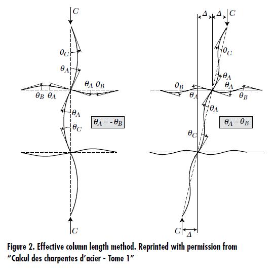
QUESTION: (SUMMER2012) I have used the effective-length method to design columns in sway-permitted frames as well as those in sway-prevented frames. But I cannot find the effective-length nomograph for sway-permitted frames in CSA Standard S16. Is the effective-length method still valid?
ANSWER:
The effective column length method attempts to approximate the elastic critical column load for a regular frame that is without primary moments and consists of identical beams in each level and identical columns (see Figure 2). This idealized frame model does not account for any second-order effects in the beams at all. Moreover, in comparison with modern analysis methods that account for second-order effects etc., it usually fails to provide accurate results for real frames. Since the introduction of S16.1-M89, the Standard has abandoned the effective length design method for sway-permitted frames. Accordingly, the nomograph for sway-permitted frames has since been excluded.
When an elastic analysis is used, the current standard, S16-09, requires the application of a second-order analysis that directly accounts for sway effects. Alternatively, P-delta effects are included using the amplification factor, U2. In addition, notional loads are applied to account for the effects of partial yielding and initial out-of-plumbness.
Note: When P-delta effects and notional loads are accounted for, the use of an effective column length for sway-prevented case (K ≤ 1) is permitted for consideration of lateral-torsional buckling. However, it is assumed in the effective length method that all members remain elastic prior to buckling. Hence the strong-column-weak-beam requirements for non-conventional construction, where applicable, may render its use inappropriate.
QUESTION: (SPRING2012) When I use the amplifier, U2, to account for P-Δ effects in accordance with S16, should I apply U2 to amplify the notional loads as well?
ANSWER: Yes, notional loads should also be amplified when U2 is used to account for P-Δ effects.
QUESTION: Part A: (FALL2011) How do I calculate the axial compressive resistance of a member subject to elastic local buckling?
ANSWER: Two methods are provided in CSA Standard S16-09, the effective area method and the effective yield stress method.
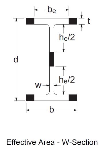
Effective area methodEngineers are generally familiar with the concept of effective area when designing columns subject to elastic local buckling. Such sections are expected to undergo local buckling before reaching the yield load in axial compression, AFy. They are designed in accordance with CSA S16-09 Clause 13.3.5 (a) whenever the width-to-thickness ratio of the flanges or web exceeds the limits given in Table 1 of S16-09. When calculating the axial compressive resistance, a portion or portions of the cross-section is considered ineffective and is therefore omitted. Considering a wide-flange section, for example, the effective cross-sectional area, Ae, is computed as follows: If the flanges exceed the maximum width-to-thickness ratio of Table 1, the area of the tips (shaded parts in the figure shown) is removed, such that the remaining effective flange width, be, meets the maximum ratio; similarly, the effective web depth is taken as he as shown in the figure. The effective portions of the flanges and web together make up the effective area, Ae.
Effective yield stress method
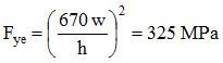
Perhaps less familiar is the effective yield stress method, which S16-09 also permits for calculating the axial compressive resistance. According to this concept first introduced in S16-01, the cross-sectional area remains intact, but the yield stress is reduced to account for local buckling. The effective yield stress, Fye, is taken as the reduced yield stress determined from the width-to-thickness ratio meeting the limit in Table 1. If both the flanges and the web are subject to elastic local buckling, two separate effective yield stresses are calculated. For simplicity, the member resistance is based on the lower of the two values.
QUESTION: Part B: (FALL2011) Do the methods provided in CSA S16-09 give the same answer?
ANSWER:
ANSWER: No, the effective area method and the effective yield stress method, in general, do not give the same answer. An example is presented below to illustrate both methods. Consider a laterally supported W360x72 column (L = 0) made of ASTM A992 steel. The cross-sectional area is A = 9100 mm2 and the specified yield stress, Fy, = 345 MPa. The factored axial compressive resistance will be determined on the basis of (1) effective area and (2) effective yield stress.
(1) Effective area methodCheck the width-to-thickness ratios of the flanges and web:
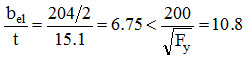 The flanges are not subject to local buckling.
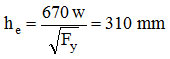
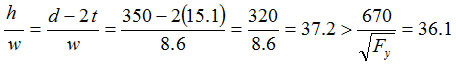 The web is subject to elastic local buckling. The effective web depth is given by:
 The effective area is:
 And the compressive resistance is:
QUESTION: Part C: (FALL2011) Which method is used to calculate the values for sections subject to elastic local buckling in the Column Tables and Angle Strut Tables in the CISC Handbook?
ANSWER: Both methods are used to calculate the factored compressive resistances, Cr, for W-columns subject to elastic local buckling and the tabulated values are the larger of the two. Only the effective area method is used to calculate the Cr values for other columns and struts. Angle sections that exceed the maximum b-to-t limit in Table 1 are excluded from the star-shaped angle strut tables.
QUESTION: (SUMMER2016) For wide-flange sections used for building construction, should I specify CSA G40.21 Grade 350W or ASTM A992?
ANSWER: ASTM A992/992M should be specified. It is the grade that North American wide-flange mills produced to and CSA Standard S16-14 (and S16-09) explicitly recognize. Introduced in the 1990s as a product with enhanced properties for seismic applications, A992 is produced to additional controls for mechanical properties, such as a maximum yield stress limit and a maximum yield-to-tensile strength ratio. ASTM A992/992M steel is also preferred for greatest sourcing flexibility although mills in North America would certify their products destined for Canada to CSA G40.21 350W as well as ASTM A992/A992M.
QUESTION: (FALL2015) I am involved with the design of an unenclosed industrial structure for which neither the building code nor the bridge code applies. Should I specify notch-tough steel? Are notch-tough W-shapes available? How do I determine the appropriate level of notch-toughness?
ANSWER: Brittle fracture is a complex subject. In order to limit the probability of its occurrence to an acceptable level, one should account for the consequence of failure together with many influential factors as described in Annex L of CSA S16-14. Notch toughness of steel is only one of these factors. Often, fracture control for structures other than buildings and bridges involves identifying the safe options then choosing the most viable solution. Hence the engineer(s) who is responsible for the design, construction specifications and supervision, QA, QC, recommendation for future inspections, etc. is in the best position to make this decision.
With respect to steel grades and their availability, this is the current situation. Although common structural steels, such as CSA G40.21 Types W and A steels generally possess notch toughness that is superior to many steel products used for non-structural applications, they are not produced to meet specific impact testing requirements. Types WT and AT steels are. Purchasers of Types WT and AT steels must also specify the required notch-toughness category that establishes the Charpy V-notch test temperature and energy level. Similarly, purchasers of ASTM steel grades, such as A992, must specify the appropriate test temperature and energy level if they so desire. To our knowledge, a North American mill produces W-sections up to about 440 kg/m to notch-toughness requirements comparable to CSA 350WT Cat. 3. It should be noted that Charpy V-notch test requirements add cost and lead time. Therefore, they should not be specified indiscriminately.
QUESTION: (SPRING2012) When CSA G40.21 300W steel strip is specified as the material for light braces in a building structure, can commercial grade steel products be used instead? What if they are supplied with a test report showing yield stress values matching or exceeding 300 MPa?
ANSWER: No. The reasons include:
a) Commercial grade steel sheet and strip are not produced to meet mandatory mechanical properties, such as minimum yield point, tensile strength and elongation; and
b) Strength levels reported on mill test certificates should not be used as the basis for design. See Clause 5.1.2 of CSA Standard S16-09.
QUESTION: (2015) What are the most common grades for structural steel shapes and sections used in building construction?
ANSWER: The main contributing factors are: a) their suitability for the intended applications as recognized by codes and standards, and b) availability. A summary for common structural steel grades used for building construction is shown in the table below:
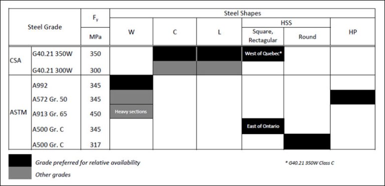
It should be noted that an A500 HSS is not an exact substitution for its G40.21 350W counterpart having the same nominal size designation, mainly due to the less stringent ASTM A500 under-mass tolerance and, in some cases, lower tensile strength properties.
QUESTION: (FALL2015) I am involved with the design of an unenclosed industrial structure for which neither the building code nor the bridge code applies. Should I specify notch-tough steel? Are notch-tough W-shapes available? How do I determine the appropriate level of notch-toughness?
ANSWER: Brittle fracture is a complex subject. In order to limit the probability of its occurrence to an acceptable level, one should account for the consequence of failure together with many influential factors as described in Annex L of CSA S16-14. Notch toughness of steel is only one of these factors. Often, fracture control for structures other than buildings and bridges involves identifying the safe options then choosing the most viable solution. Hence the engineer(s) who is responsible for the design, construction specifications and supervision, QA, QC, recommendation for future inspections, etc. is in the best position to make this decision.With respect to steel grades and their availability, this is the current situation. Although common structural steels, such as CSA G40.21 Types W and A steels generally possess notch toughness that is superior to many steel products used for non-structural applications, they are not produced to meet specific impact testing requirements. Types WT and AT steels are. Purchasers of Types WT and AT steels must also specify the required notch-toughness category that establishes the Charpy V-notch test temperature and energy level. Similarly, purchasers of ASTM steel grades, such as A992, must specify the appropriate test temperature and energy level if they so desire. To our knowledge, a North American mill produces W-sections up to about 440 kg/m to notch-toughness requirements comparable to CSA 350WT Cat. 3. It should be noted that Charpy V-notch test requirements add cost and lead time. Therefore, they should not be specified indiscriminately.
QUESTION: (2014) Are ASTM A1085 products readily available?
ANSWER: ASTM A1085 is a new standard, introduced in 2013. Atlas Tube Canada ULC has started taking orders in 2013. Time will tell if they will be readily available from service centres.
QUESTION: (SUMMER2011) Why have Welded Wide Flange (WWF) shapes been commonly used in Canada?
ANSWER: The introduction of CSA G40.12 in 1964 marked the beginning of an era for Canadian structural steel. This stronger (300 MPa specified yield) steel replaced ASTM A36 (248 MPa yield) steel as the basic grade for wide-flange shapes, etc. Algoma Steel, the Canadian wide-flange mill at that time, did not produce the full range of W-sections. As a result, the welded wide-flange (WWF) sections were introduced as alternatives for heavy rolled sections.As built-up shapes, the WWF cross-sections can be tailored for optimal efficiency; standard beam sections were compact sections or stockier and all columns were Class 3 or stockier. Because the plates were oxy-flame-cut in Algoma’s facility, their WWF sections were also qualified for the most favourable column design curve (of the three SSRC curves), whereas the least favourable curve applied to heavy A36 W-shapes.The above-mentioned advantages, coupled with the higher strength of the 300 MPa steel, had helped WWF sections to remain popular choices for heavy sections until ASTM A992 (345 MPa specified min. yield) emerged as the common North American steel grade for wide flange shapes about a decade ago. Until recently, WWF sections also benefited from the availability of notch-tough steel plates where required, while rolled shapes, supplied to meet certain notch-toughness requirements, were scarce. Rolled W-shapes, up to 440 kg/m in weight and meeting CSA Type T Category 3 notch-toughness requirements, are now available (subject to minimum tonnage order, etc.). All in all, the clear advantages that WWF shapes once offered have dwindled.
QUESTION: (SUMMER2011) Essar Steel Algoma has closed their WWF production facility. What are the steel designer’s choices?
ANSWER: For several years, another source of WWF sections had supplied the market in western Canada. Following Essar Steel Algoma’s exit, a large fabrication facility in eastern Canada has shown interest in WWF production. The future availability of WWF sections, or lack of, will be sorted out in the marketplace. It should be noted that WWF sections are essentially standardized welded built-up H-shapes (see answer to the question below). Hence they can be replaced with custom-designed welded built-up sections.Here are the current choices: a) North American mills produce ASTM A992 rolled W-shapes up to 1,100 mm in depth, and column sections weigh up to 1,086 kg/m. At current exchange rates, they ought to be very competitive; and b) Welded plate girders for sections deeper than 1,100 mm and where the need to camber heavy rolled girders renders them unsuitable.
QUESTION: (FALL2015) I am involved with the design of an unenclosed industrial structure for which neither the building code nor the bridge code applies. Should I specify notch-tough steel? Are notch-tough W-shapes available? How do I determine the appropriate level of notch-toughness?
ANSWER: Brittle fracture is a complex subject. In order to limit the probability of its occurrence to an acceptable level, one should account for the consequence of failure together with many influential factors as described in Annex L of CSA S16-14. Notch toughness of steel is only one of these factors. Often, fracture control for structures other than buildings and bridges involves identifying the safe options then choosing the most viable solution. Hence the engineer(s) who is responsible for the design, construction specifications and supervision, QA, QC, recommendation for future inspections, etc. is in the best position to make this decision.
With respect to steel grades and their availability, this is the current situation. Although common structural steels, such as CSA G40.21 Types W and A steels generally possess notch toughness that is superior to many steel products used for non-structural applications, they are not produced to meet specific impact testing requirements. Types WT and AT steels are. Purchasers of Types WT and AT steels must also specify the required notch-toughness category that establishes the Charpy V-notch test temperature and energy level. Similarly, purchasers of ASTM steel grades, such as A992, must specify the appropriate test temperature and energy level if they so desire. To our knowledge, a North American mill produces W-sections up to about 440 kg/m to notch-toughness requirements comparable to CSA 350WT Cat. 3. It should be noted that Charpy V-notch test requirements add cost and lead time. Therefore, they should not be specified indiscriminately.
QUESTION: (SUMMER2016) In National Building Code of Canada 2015, the period dependant Site Coefficient F(T), used for determination of seismic Design Spectral Accelerations, has replaced Site Coefficients Fa and Fv. CSA Standard S16-14, however, continues to reference Site Coefficients, Fa and Fv. Is S16-14 out of step with NBC 2015?
ANSWER: CSA S16-14 is compatible with NBC 2015. In S16-14, coefficients Fa and Fv, appear in two expressions: the short-period specified spectral acceleration ratio, IEFaSa(0.2), and the one-second specified spectral acceleration ratio, IEFvSa(1.0). Certain values of these quantities serve as triggers for more stringent requirements whereas other values set the conditions for relaxation. Although F(T) has replaced Fa and Fv for the purpose of determination of Design Spectral Accelerations in NBC 2015 the Code retains the expressions IEFaSa(0.2) and IEFvSa(1.0) as triggers. As defined in Sentence 4.1.8.4. (7) of NBC 2015, Fa = F(0.2) and Fv = F(1.0). Ideally, F(0.2) and F(1.0) should also replace Fa and Fv respectively in these trigger expressions. This was not possible in the 2015 code cycle for the following reason: In order to be considered for adoption by NBC 2015, CSA material design standards, S16, A23.3 etc., must be published in 2014. However, changes proposed for NBC, including the period dependant Site Coefficient F(T), could not be finalized in time to meet the publication schedule for the CSA standards.
QUESTION: (FALL2012) When designing bolted connections, are seismic loads considered to be static or cyclic?
ANSWER:The Seismic Corner article entitled “Bolted Connections for Seismic Applications” in CISC publication, Advantage Steel No. 31 (Summer 2008), outlined the requirements for bolted connections for seismic applications in accordance with S16-01. The article is available at: https://cisc-icca.ca/ciscwp/product/advantage-steel-no-31/
In NBC 2010 and S16-09, the building height restriction for Conventional Construction where the specified short-period spectral acceleration, IEFaSa(0.2), exceeds 0.35 has been increased. The above mentioned requirements for bolted connections also apply to these taller structures of Conventional Construction.
QUESTION: (SPRING2012) The User’s Guide – NBC Structural Commentaries provides external peak pressure-gust coefficient values, in Figures I-8 to I-14, for design of cladding and secondary structural members. Should these values or those tabulated in Figure I-7 be used for the design of a primary roof girder in a low-rise building?
ANSWER: The values tabulated in Figure I-7 apply to the design of lateral-load resisting systems for low-rise buildings when wind load acting simultaneously on all surfaces is considered. In the NBC Structural Commentaries, the wind effects in such loading conditions are termed “primary” structural actions whereas structural members subjected to local external pressure (or suction) are referred to as “secondary” members. Local peak gust pressure/suction values are significantly larger than the effective gust pressure acting on the whole building. Therefore, the coefficient values in Figure I-7 should not be used for the design of a roof girder unless it is a member of a rigid frame or a part of a braced frame and the effects due to “primary” wind actions govern the design.
CISC provides the FAQ section as a part of its commitment to the education of those interested in the use of steel in construction. Neither CISC nor the authors assume responsibility for errors or oversights resulting from the use of the information contained herein. Suggested solutions may not necessarily apply to a particular structure or application, and are not intended to replace the expertise of a professional engineer, architect or other licensed professional.