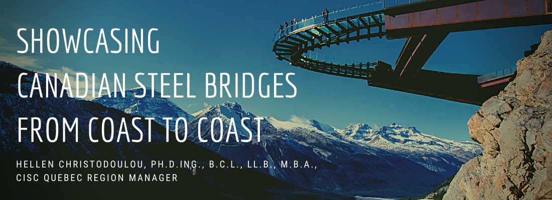
By Hellen Christodoulou, Ph.D.ing., B.C.L., LL.B., M.B.A., CISC-ICCA Quebec Region Manager
Founded in 1930, the CISC-ICCA (The Canadian Institute of Steel Construction) operates as a technical, marketing and government relations organization representing the Canadian Steel Industry; it is Canada’s voice for the steel construction industry, providing leadership in sustainable design and construction, efficiency, quality and innovation.
The CISC promotes the use and benefits of steel in construction, adds value to the design and construction community and supports the needs of the membership and industry through technical expertise, knowledge transfer, research and development, industry codes and standards, certification, and advocacy.1
Across the Canadian provinces, the CISC-ICCA Regions hold Design Award Competitions every two years, with Quebec being the exception holding them annually. During the Galas the CISC-ICCA Regions reward teams who carry out exceptional projects in steel, one of the categories being “Bridges”.
The Design Award Galas showcase steel construction projects for their beauty, uniqueness and originality. The nominated project and project teams, selected by a prominent jury, receive special congratulations and special recognition during these events. Each team member, such as the Architect, Engineer, Steel Fabricator, Detailers. etc. receive a commemorative plaque to mark the occasion.
There have been many bridges that have been awarded this prestigious award and this article highlights some of the most noteworthy selections.
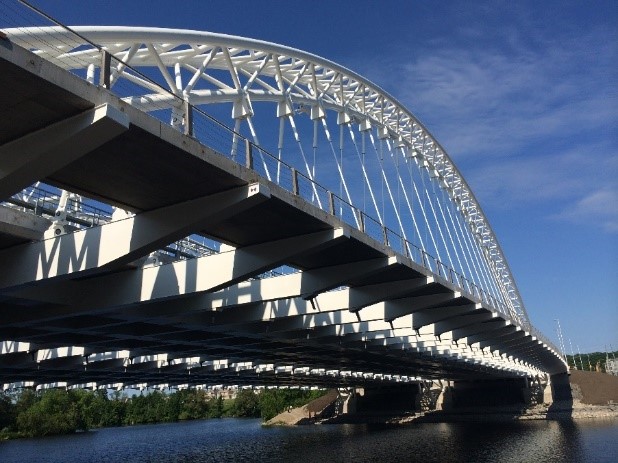
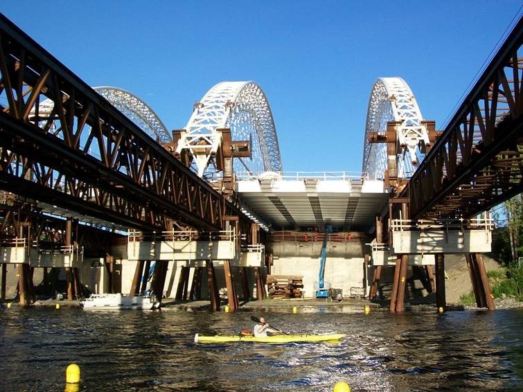
THE STRANDHERD-ARMSTRONG BRIDGE
Project Team
Engineer: Harbourside Engineering Consultants
Bridge Designer: Parsons (formerly Delcan)
General Contractor: Horseshoe Hill Construction
Steel Erector: Montacier International
Steel Fabricator: Cherubini Metal Works
Steel Detailer: Tenca Steel Detailing
The Strandherd-Armstrong Bridge, located south of Ottawa, connects the communities of Riverside-South and Barrhaven, between Strandherd Road and Earl Armstrong Street.
This new link promotes the development of these communities, reducing travel times and improving the public transport offer. It offers easier access to services, businesses and jobs, as well as schools and recreation areas. It also contributes to the improvement of the Ottawa area network.
The Bridge has a total length of 143 meters and the arches rise to 21 meters above the roadway and have a 125-metre opening. The lightness, strength of the material and its flexible use, permitted aerial launch work that could not have been implemented.
The environmental objectives and the respect for this heritage site were certainly governing factors. The goals were achieved and undoubtedly exceeded, steel made this exceptional structure possible.
The bridge supports four lanes of traffic, one of which is dedicated to public transport, and one cycle lane per direction taking place between the three arches. Two sidewalks, outside the arches, complete the cross section. The large width of the deck – 54.7 m abutment and 58.7 m in the center – is mitigated by the spaces provided for the passage of the arches, promoting natural lighting of the banks under the deck.
The structure has a total length of 143 m. The arches, culminating at 21 m above the roadway, have an opening of 125 m. Each arc is constituted by a lattice of tubes forming a triangle of 4.25 m wide by 3.50 m high for the central arc and 3.50 m by 2.50 m for the lateral arches.
The tubes, 508 mm in diameter, are bent with a radius of about 90 m. The two upper tubes are interconnected by spacers “K” and with the bottom chord by diagonal spacers. These spacers, also in tube, have a diameter ranging from 219 mm to 273 mm.
On the central hundred meters, these arches support a mixed deck through twenty-five pairs of lines. With the exception of the first two and last lines, in tube, all the others are cables composed of waxed sheathed galvanized strands, with seven strands for the suspension of the road parts and four for those of the bridges.
At the ends, between the last line and the abutment, the deck is supported by steel columns resting on the support mass of the arches.
The concrete slab, 225 mm, is supported by a grid made of steel boxes in both directions. In the current zone, the transverse boxes are rectangular, with a width of 500 mm and a height of 900 mm.
The spar caissons have a trapezoidal shape, with a base of 1200 mm and a height of 900 mm. The thrust of the arches is transferred to the foundation by concrete thrust blocks associated with the abutment. This system is based on fifteen boxes of 1.80 m in diameter anchored to the rock.
Once the central part of the structure – deck, arches and lines were assembled on temporary supports, temporary transfer beams were installed at the ends of the arches and connected by cables to balance the thrust. The temporary supports were then removed, arches loaded, and the structure was “slipped” on a system of rails supported by river booms.
Once this operation was complete; the ends of the arches were added, and the rail system was removed. The structure was then lowered on its thrust blocks, allowing the removal of the balancing cables and the transfer blocks.
THE PEACE BRIDGE
Project Team
Architect: Santiago Calatrava LLC
Structural Engineer: Santiago Calatrava LLC/Stantec Consulting Ltd.
Project Manager / General Contractor: Graham Infrastructure Ltd.
Erector: Norfab Mfg. (1993) Inc
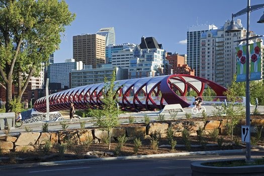
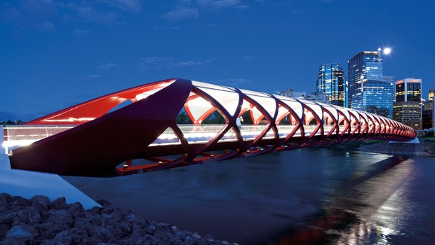
The Peace Bridge spanning the Bow River in Calgary has become a favorite with photographers since it opened in May 2012.
Designed by world-renowned architect Santiago Calatrava, the stunning structure is a pedestrian/cyclist bridge that connects the vibrant neighborhoods of Sunnyside and Hillhurst to the city’s downtown core.
It has become an instant icon of the city and has vitalized the surrounding neighborhoods.
It is crossed by about 6,000 people daily, including a growing number of people using alternative modes of transportation to their workplaces as well as recreational users. The bridge is a popular spot for photo shoots and has become one of the prime meeting points in Calgary.
The bridge structure is a sleek helix-shaped steel truss system developed over a semi-elliptical cross-section in a single span of 126 meters. The deck is eight meters wide to accommodate pedestrian lanes on either side and a central bike lane separated by curbs.
The location of the bridge presented a design challenge that made structural steel the ideal solution. The Bow River at that point is about 120 meters wide and six meters deep.
For environmental and safety reasons, an in-stream support pier was not an option. This meant the bridge would need to comprise a single 126-metre-long span.
The site is also beneath the flight path of Calgary’s downtown heliport. Flight path restrictions, in combination with limitations due to the Bow River’s 100-year flood levels, squeezed the allowed structural depth of the bridge to a maximum of only 5.85 meters.
Due to the challenging design criteria of a long span, wide bridge deck, and low structural depth, structural steel was chosen for its high strength-to-weight ratio.
The bridge structure is symmetrical along the center of the deck section, with the two identical halves connected at the top and bottom chords.
This symmetry and repetition in design elements allowed the bridge to be prefabricated in numerous manufacturing facilities and assembled in a single on-site shop.
BURGOYNE BRIDGE
Project Team
Fabricator: Walters Group/ Canam Group
Detailer: Walters Group/ Tenca Steel Detailing, Inc.
Erector: Walters Group
Engineer: Parsons Owner: Niagara Region
General Contractor: Pomerleau
Deck Contractor: Vixman Construction Ltd.
One of the main landmarks of the 1915 city of St. Catherine is now history. The Niagara Region and the City of St. Catherine wanted to replace the Burgoyne Bridge with an aesthetic structure that could be considered a signature, even emblematic work for the area, while respecting the heritage aspect of the site.
The Burgoyne Bridge is a vital link in the city of St. Catherine and since the structure was over 100 years old, it needed to be replaced with a new structure, with the restriction of having no disruption to traffic.
The original structure of the Burgoyne Bridge was a steel lattice girder and concrete deck located on the same foundations as the new structure on the west side.
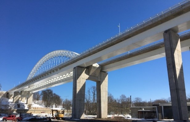
The bridge is comprised of seven continuous bays with a total length of 380 meters including a 125-meter and 85-ton section long arch, spanning the Twelve Mile Creek and Highway 406.
The span of the arch consists of a simple lattice arch with two trapezoidal box girders projecting from each side and suspended steel cables on either side of the transverse floor beams.
The six spans of the approach, ranging in length from 20 to 44 meters, are made of two trapezoidal steel box girders covered with reinforced concrete decks. The superstructure is supported by large reinforced concrete pillars and reinforced by reinforced concrete foundations.
The constraints of the valley and existing roads being unconventional, lead to more challenges and creativity for the construction of this bridge. In addition, the superstructure was to be built without interruption of traffic on the existing bridge or the provincial highway passing underneath.
Moreover, the size of the beams and the limitations on the site prevented the use of a large crane under the bridge.
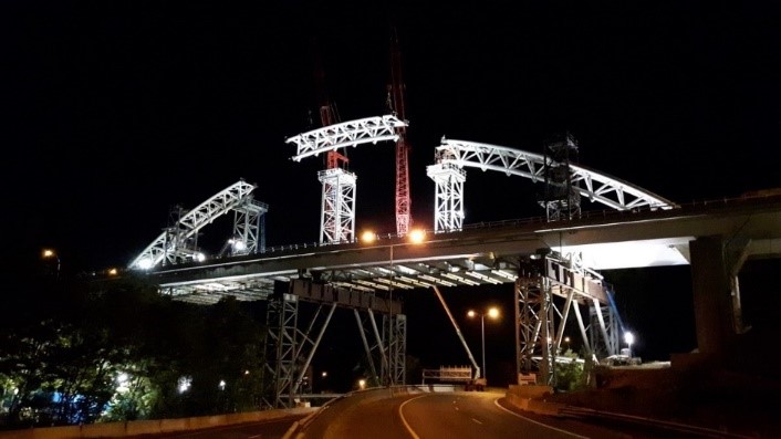
So, instead of erecting the structure in a conventional way, the progressive method of launching the beams was used pushing each of the beams all along what has already been built.
Completion of the installation of the first beam lasted 59 days throughout the winter. Once this span was in place, two traffic lanes were opened on the new structure and the old structure was removed, allowing the continuity of the circulation throughout the erection of the second span and the triangular arch.
The 32 beams were assembled sequentially where, two by two, the beams were bolted together, placed on the bearings supported by pillars.
Temporary steel towers supporting the structure of the arch during erection were put in place and then removed once the project was completed. The very well-organized erection was made during the night when the highway below was closed.
ALLUMETTES BRIDGE
Project Team
Structural Engineer: Delcan, a PARSONS Company & DPHV
Project Manager / General Contractor: Pomerleau
Fabricator: Canam-Ponts, division de Groupe Canam
Detailer: Tenca Steel Detailing Inc.
Erector: Montacier
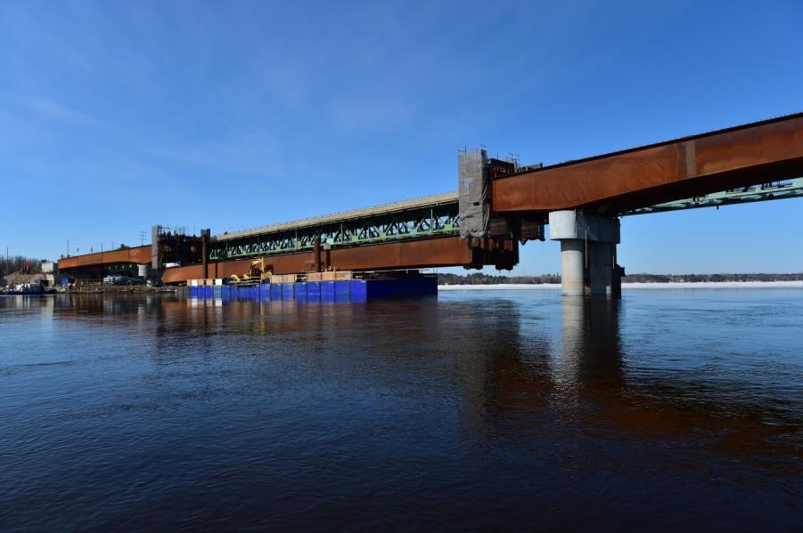
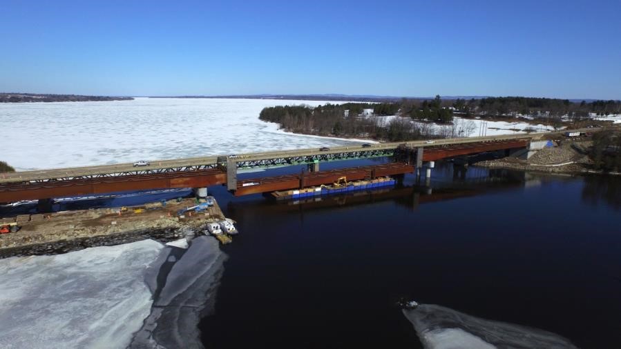
This 280-meter long road bridge replaced the Allumettes Bridge over the Ottawa River main canal southeast of Pembroke, Ontario, connecting the province of Ontario and the city of L’Isle-aux-Eaux. -Allumettes, in Quebec.
The structure, consisting of two box girders cut into 22 segments, comprises 1,880 tonnes of steel components. The complexity of this project is characterized by the high weight of box beams up to 91 tonnes and its tight schedule. The bridge was commissioned in August 2015.
The design of this structure over the Ottawa River presented several major challenges, including environmental constraints, the proximity of the existing bridge and the presence of a geological fault at the bridge.
During the design phase, the option to reduce the number of piles in relation to the existing bridge was chosen by the owner as this limited the environmental impacts of the project.
Optimization of the concept led to the choice of a variable-inertia steel caisson bridge, continuous over three spans, including a main span of 10 meters and two 85-meter bank spans.
Considering the location of the bridge and the tight construction schedule, a steel structure had the double advantage of being able to be quickly built in fabricator plants and then transported by truck for assembly during all year periods.
The use of beams with variable inertia, in addition to allowing the optimization of the use of the material, gave a slender and harmonious aspect to this large structure.
The presence of a geological fault at the right of the structure represented an important stake during the design.
As a result of multimodal modeling and seismic analysis of the bridge, caisson piles with rock socket were retained for the pile foundations. Seismic isolators were incorporated to reduce the impact of an earthquake on the structure.
In addition, special control measures had to be taken to ensure that the sockets of the caisson piles had the necessary length to withstand the forces while remaining in the sound rock zone, without encroaching on the shear zone of the fault characterized by a highly fractured rock
The main beams were erected using a combination of conventional methods and atypical methods: the edge spans were erected from temporary piers, using mobile cranes and temporary piers, while the assembly the central section of 90 meters in length was made by jacking the two box beams simultaneously from a barge.
Since the structure is continuous, the beams had to be lifted about 1.3 meters to the abutments to achieve geometric compatibility allowing the bolting of construction joints.
The required erection method involved the use of a 400-metric-ton crawler crane, temporary supports, several jacks, and a 1.3-meter abutment lift to connect the splices in the center section.
The use of a steel frame was the large contributor to the success of the project, which was completed in less than 18 months, the main assembly of the structure was done in the heart of winter, thereby saving precious months, without stopping work.
Once the bridge was fabricated, the team entered a time trial race with the general contractor to complete the assembly before the spring breakup. Given the bathymetry conditions of the Ottawa River at this location, a temporary barge bridge was put in place, making assembly of the structure more complex.
To respect the schedule, it was decided in the preliminary draft not to fabricate the structure in a linear way as usual, but rather to manufacture the box girders according to the assembly order desired by the general contractor.
This required particular logistics during the fabrication of the components, which made it possible to deliver the beams in time. The design team was also forced to adapt to the singularity of this project by partitioning the shipment as soon as the drawings were approved to allow for a rapid production.
The weight of some beams reached more than 90 tons, exceeding the lifting capacity with the fabricator’s plant, therefore Engineers were asked to find a solution for moving these parts.
The team of experts therefore set up a system consisting of hydraulic cylinders and rollers that made it possible to slide each of the boxes out of the factory without having to use the cranes. Beams were shipped to the site, as soon as the fabrication was complete, so as not to delay assembly.
Challenges were even more complex than anticipated, as some restrictions issued by the Department of Transport, such as height, weight, or certain traffic barriers due to construction, were not known at the outset. All challenges were met and the project was successfully completed.
HUNT CLUB PATHWAY CONNECTION TO THE SOUTHEAST TRANSITWAY
Project Team
Structural Engineer: Delcan, A Parsons Company
Project Manager / General Contractor: Louis W. Bray Construction
Fabricator: Canam-Ponts, division de Groupe Canam
Detailer: Canam-Ponts, division de Groupe Canam
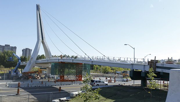
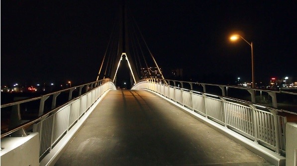
This 246-foot-long (75 meters) pedestrian bridge was erected over the Ottawa Airport Parkway to link the Hunt Club community and the Southeast Transitway in Ottawa, Ontario. The structure is a cable-stayed bridge with two asymmetrical spans, one of 170 feet (52 meters) in length and the other 76 feet (23 meters) in length. The deck is composed of three orthotropic steel deck panels. The bridge opened to pedestrians and cyclists in November 2014.
Initially, the bridge was not designed with a steel deck. Because of a weight issue, however, it was essential to lighten the superstructure. A lightweight, economically feasible and durable deck had to be developed and erected, within a very short timeframe.
With special collaboration from Parsons, an orthotropic steel deck proved to be the ideal solution. Such a deck can be up to two times lighter than a similar concrete deck and is designed for a service life of more than 75 years. It is manufactured and takes very little time to erect at the job site.
The fabrication of the orthotropic steel deck was entrusted to Canam-Bridges. It was a challenging project on several fronts. Special care had to be taken with fabrication methods, in-plant handling and welding sequences, given the dimensions of the three deck sections and their relative flexibility during the fabrication process. It was particularly important to control the deformations induced by welding operations of secondary elements to the top plate of the deck.
For the thin wearing surface, the use of Bimagrip, a highly resistant polyurethane-based product with an aggregate top layer, helped decrease the structure’s overall weight and speed up on-site work. Because this type of wearing surface is installed at the fabrication plant, there is no need to wait until the panels are erected on site and then apply the surface course, therefore reducing the construction schedule.
Once the fabrication of the deck was completed, there was a challenge remaining: delivering 19-feet-wide (5.775 meters) deck sections. Transporting such wide loads requires coordination over the entire trip, and more specifically between the transport companies and various entities such as the Quebec’s Ministry of Transportation, cities of Quebec City, Montréal and Ottawa, and the Ministry of Transportation in Ontario.
Efficient planning and excellent cooperation between the various actors made it possible to deliver the deck sections on time.
The orthotropic steel deck supplied by Canam-Bridges significantly reduced the weight of the structure and contributed to successful completion of the project. The decision to use a steel deck allowed addressing the various design and building challenges while meeting the extremely tight schedule of the project.2
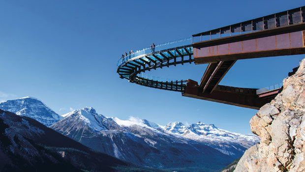
GLACIER SKYWALK

Project Team
Fabricator: Beauce Atlas Steel Fabricators
Engineers: Read Jones Christoffersen Ltd.
In the fall of 2010, Brewster Travel Canada issued an Expression of Interest request for design build teams to create a new and exciting tourist attraction.
They wanted to create an experience that would attract people from around the world to Jasper National Park. “Gobsmacked” and “Visceral” were terms Brewster used to describe their expectations. The resulting Glacier Skywalk is a thrilling and dramatic structure featuring 30m of curved glass walkway extending 30m beyond the cliff face and suspended 280m above the Sunwapta River.
By cantilevering the structure, Read Jones Christoffersen Ltd., as design lead and structural engineer, was able to deliver the unique and exhilarating experience they wanted while blending the Skywalk in with the natural environment.
The Brewster company, which operates various tourist sites in the Rocky Mountains, began and started in 2012 the construction of this observation bridge whose half-moon end composed of a floor and glass railings allowing spectacular sighting on the Sunwapta River and the Athabasca parish priest.
This bridge is embedded on a cliff sidewall mounting on a slope of 280 meters and with a 45-meter cantilever.
Brewster engaged the services of the RJC Consulting Engineer located in Calgary to execute the structural plans and specifications. They chose a structure of steel caissons of variable geometry to support the half-moon-shaped glass bridge with a radius of 10 meters at the end of these caissons and attached to blocks of glass, with anchors weighing 10 imperial tons each at each end.
The overhang of the two box girders was 35 meters and 15 meters. The ratio of the dead weight of the steel versus its high resistance convinced the professionals to use Steel as the material for this structure overhang which respected the allowed and anticipated deflections.
The box structure remained apparent “uncoated”. The client opted for a finish showing the raw appearance of steel exposed to the elements and blending into the rocky landscape. The atmospheric steel was therefore chosen and retained for the execution of the caissons and secondary floor structure.
The constructability challenge was to not exceed the weight and size limits for transporting and erecting these Parts. The contractor PCL awarded the contract to Constructions Beauce Atlas in June 2012 for the supply and delivery of the box girders, transverse beams and secondary beams.
This project located 4,200 km from the Beauce Atlas facilities in Ste-Marie of Beauce was in itself a challenge because of the distance separating the fabricator plant from the site and also because the assembly granted by the customer directly to a steel fitter included a logistics and a schedule set at quarter of tower that had to be respected because otherwise would have caused significant impacts.
Beauce-Atlas was very much involved in the design from the beginning of the project to ensure the feasibility of the project and find the best options for the fabrication, delivery and assembly of these parts.
The splices of the caissons were therefore established jointly in order to limit the weight. The longest box consisted of 4 sections including 2 weighing 70 tons imp. and the other 2 50 tons imp. They ranged in size from 26 to 50 feet by 12 feet tall and 10 feet wide. The shorter box consisted of 2 sections of 40 and 45 tons imp. with a length of 38 and 40 feet, a height of 9 feet and a width of 10 feet.
The splices were made of bolted plates however the first two caissons of the longest caisson deposited on the anchoring groups in tension and compression had to be welded in addition and due to the efforts too great.
This type of project required precision in shop drawings and in the fabrication to be identical to the bridge project intended. The preparation of the plans and shop drawings were prepared by Génifab in Quebec City, a company specializing in the design of bridges and special projects.
The fabrication was done at the Beauce Atlas Ste-Marie plant and part of the fabrication contract was subcontracted to Metacor in Terrebonne.
The limitation of the deformations during the welding of the caissons, the precision of the workpieces constituted the main challenge for the fabrication process. A pre-assembly of the elements had been done in the plant in order to ensure the conformity of all fabricated elements.
The project was erected in the summer of 2013 and completed in the fall of 2013. The access is closed during the winter and the project was therefore opened and inaugurated in May 2014.
It was a truly success right from the start. Great words of praise have been received by all members of the team. This project offers a publicized, public and touristic showcase of an accomplishment achieved through the availability and use of steel materials on the Canadian market.
THE CRAIGFLOWER BRIDGE

Project Team
Architect: Hughes Condon Marler Architects
Structural Engineer: Herold Engineering Limited
Project Manager / General Contractor: Don Mann Construction Limited
Fabricator: Surespan Structures Limited
Detailer: Exact Steel Detailing Limited
Erector: Ruskin Construction Limited
The Craigflower Bridge has been in operation since the early colonial days of Victoria, and this recent replacement is believed to be the fourth bridge on this site.
As part of the Hudson’s Bay Company’s historic Craigflower Farm, the bridge served as a transportation link between Craigflower School and Craigflower Manor, both National Historic Sites. The bridge site also has unique archaeological merit, encompassing three distinct periods and types of human habitation which span thousands of years.
Herold Engineering was selected as the Prime Consultant and bridge designers for the project for the Municipality of Saanich and the Town of View Royal who were dual owners of the bridge.
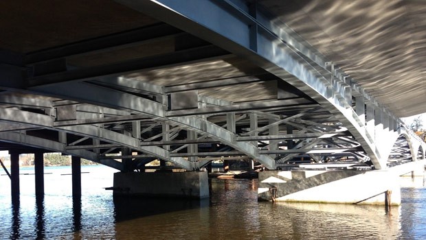
The 120-metre-long bridge replaces a very narrow and busy 80-year-old two-lane creosoted timber trestle bridge with a four-span structure using continuous Vierendeel steel trusses and a non-symmetric partial precast and composite cast-in-place concrete deck that varies from 20 m to 22 m.
Being in a semi-marine environment, it was desired that welded connections minimize the use of mouse-holes and other openings. Connections were therefore specified using a combination of CPJ and PJP weld methods.
Surespan was contracted by Ruskin Construction to supply & deliver Architectural arched steel trusses & half-depth concrete deck panels for the Craigflower bridge in Victoria, BC. The arched steel trusses were metallized to protect them from the elements and the process provides them with a lovely silvery/grey appearance. Surespan received an award from the CISC (Canadian Institute of Steel Construction) for the steel trusses.
Key challenges on the project were design, schedule, budget, traffic disruption on a very busy roadway, First Nations archeological constraints, a very environmentally sensitive marine crossing of the Gorge Waterway, and the maintaining of pedestrian access during construction, including access to both an adjacent elementary school and a secondary school.
Construction of the piers also required the relocation of existing oyster beds to adjacent areas.
DEH CHO BRIDGE PROJECT
Project Team
Structural Engineer: Sargent & Associates Engineering Ltd., Infinity Engineering Group Ltd.
Project Manager / General Contractor: Ruskin Construction Ltd.
Fabricator: Rapid-Span/Structal JV
Detailer: Tenca Steel Detailing
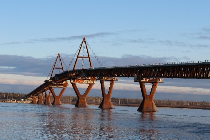
The $200 million bridge is the first built over the Mackenzie River, Canada’s longest river, and is the largest bridge project undertaken in the Northwest Territories.
The bridge provides year-round service for cars and trucks along Highway 3, connecting Yellowknife in the Northwest Territories with Highway 1 in the South.
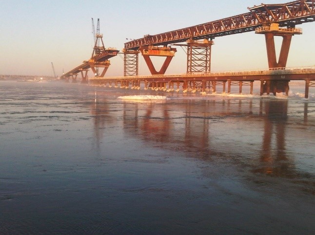
The remote location, severe winter conditions of up to -40 degrees Celsius and ambitious construction schedule, required new thinking regarding design and erection.
Ecological, lightweight bridge design principles and innovative design methods such as Assembly Line Design Approach, Failure Mechanism Concept and Fuse Design Philosophy were applied.
This led to 20% cost savings for steel and 30% for concrete. It also resulted in the world’s longest continuous superstructure, with a length of 1045 meters and expansion joints only at the abutments.
This makes the Deh Cho Bridge one of the longest continuous superstructure in North America.
The bridge is symmetrically designed. The end spans are 90 m long, followed by three spans of 112.5 m each.
The main span bridges the navigation channel and spans 190 m. The Deh Cho Bridge superstructure is designed for two lanes of traffic. Accordingly, the width of the superstructure is relative small with only 11.29 m.
The superstructure depth of 4.75 m can be described as very slender when considering the main span of 190 m which corresponds to a span to depth ratio of 40.
The two A-pylons are around 33 m above top of the piers. Each pylon supports 12 locked-coil cables with a diameter of 100 mm.
Superstructure steel is about 3,500 tons or 3.5 tons per meter bridge length. Pylon steel is relatively small and accounts for only 256 tons for both A-pylons.
The Deh Cho Bridge deck is one of the thinnest in North America with an average thickness of only 235 mm. In total we used 2,775 m^3 or around 2.7 m^3 per meter bridge length. The construction cost exceeded slightly the 200 Mio. Dollar target line. This corresponds to approximately of 18,000 Dollar per square meter.
The panels act a single span structure spanning in transverse bridge direction. Later when the in-fills are cast we will achieve composite action with the truss floor beams.
This two-way structural system is much more efficient than the one-way single span system.
Steel as a material was an excellent choice for a bridge in harsh climate conditions and at a remote site location. The degree of prefabrication and quality control that you can achieve with steel products is just outstanding and unbeatable.
The symmetrical superstructure consists of two vertical Warren trusses connected by Chevron cross frames and wind braces at top and bottom chord levels.
The articulation scheme utilizes disk bearings at the piers and abutments. The bearings guide the superstructure in the transverse bridge direction but allow longitudinal movements due to temperature changes.
Two steel A-pylons located at the tallest piers flank the navigation channel located in the bridge centre. The eight piers of the bridge are founded on concrete spread footings which are cast into the Mackenzie River bed using cofferdams.
Classified as an Extradosed Bridge System, the “open” steel box girders have significant bending stiffness and are only locally reinforced with stays and “king posts.” The Deh Cho Bridge has a very different structural behavior than similar looking cable-stayed bridges.
The superstructure design was optimized to maximize prefabrication and allow a fast-paced erection technique.
The top priorities were robustness, durability and the ease of inspection and maintenance. The goal was to achieve the highest returns on investment over the next 75 years of service.
The Deh Cho Bridge project is a lighthouse of the bridge engineering discipline.
It also provides evidence that modern progress in an industrialized society is possible in a responsible manner and in harmony with Canada’s Aboriginal people and Mother Nature.
Sir Ambrose Shea Lift Bridge
Project Team
Fabricator: Canam Ponts-Divison de Groupe Canam
Engineer :Parsons
Detailer : Vet Dessin
Detailer : Les dessins de structure Tenca
Contractor : H.J. O’Connell Construction
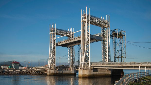
On September 23, 2016, the new Sir Ambrose Shea Lift Bridge in Newfoundland and Labrador, opened to traffic.
Located on the Avalon Peninsula in the town of Placentia, approximately 100 km west by southwest of the capital city of St. John’s, it was built as a replacement to an existing structure constructed in 1961 and As-built directly adjacent to the existing bridge.
In addition to being aesthetically pleasing with architecture reflecting the local culture and tourism potential of the region, the new bridge is designed to be durable, efficient and reliable.
The new bridge was constructed adjacent to the existing bridge to minimize disruption to navigation and road traffic. Some of the important design considerations for this new bridge were durability, efficiency and reliability.
The approximate cost of $47.7 million included construction, engineering and demolition and removal of the old bridge. The three-span bridge superstructure measures 93 meters in length and includes 1,100 tons of structural steel, including 10 girders for the approaches, and four box girders and stringers for the lift span.
The four-hollow structural tubular towers stand over 30.5 meters tall and measure 508mm wide by 25.4mm thick and they are comprised of a three-dimensional steel truss shaped representative of sails, and each tower component is connected by a three-dimensional exoskeleton truss housing the machinery operating the lift span.
Another welcoming feature was the 1.8m wide pedestrian sidewalk.
The bridge includes 9,200 meters of steel piling, 3,800 cubic meters of concrete and 150 tons of reinforcing steel. The three-span bridge includes a center movable span (vertical lift span) flanked by two simple fixed composite plate girder spans.
The functional requirements for this bridge were important considerations to the architectural features and appearance of the bridge, in view of the bridge’s high visibility in the historic community of Placentia, the town’s heritage, culture, and local environment and the importance of tourism to the local economy.
The new vertical lift bridge is comprised of three spans; a center 33m lift span, flanked by two 32m approach spans, accommodating two vehicle lanes with a sidewalk on each side. Under the lift span, the clear width of the navigation channel is 25m, with a minimum vertical clearance above high water of 3.05m when lowered and 21.34m when raised. The power and communication utilities were relocated from the existing bridge. To avoid affecting vehicular traffic and to improve alignment, the horizontal alignment of the new bridge is parallel to the existing with a 22m offset to the East.
The unique architectural features were inspired by the Salford Quays Vertical Lift Bridge in Manchester, England and include the two vertical towers on each side of the lift span. Envisioned to repre- sent boat masts and antennas, these aesthetically sleek elements emphasize verticality.
Steel tubular members make up this bridge tower silhouette. The transparent machine rooms at the helm of the towers are captivating and attention drawing. To create a focal point of interest and visibility in a harmonious contract to the dark surrounding hills, sea and sky, the color choice for the main elements of the bridge superstructure was white; a safe environment and inviting pedestrian experience, with a wider sidewalk (1.8m) in comparison with a narrow 1.2m walkway on the existing bridge.
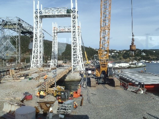
The structural steel was fabricated by Canam- Bridges and shipped from Quebec for erection, so its transportation, though challenging, was exceptionally handled by Canam-Bridges. The approximate 100-ton lift span, with some of the mechanical and electrical components of the permanent structure, was erected from a barge. The very complicated erection process required the shutting down of the marine channel.
Design had to consider transportation, erection, and long-term durability. This was achieved by designing the tower members with sealed and welded tubular pipe members. Flange bolted connections were designed to allow the contractor to fabricate the towers in manage- able segments to be transported and handled on site without the need for field welding.
This option allowed the contractor to fabricate each of the towers in 10 segments, assemble them on site, and erect them using a crane from a temporary work trestle. Bolted connections minimized the erection duration of the towers significantly, to a few days in comparison to field welding which would have required substantially more time and a significant window of good weather, which is hard to achieve at this project site.
The design team was committed to making the most effective design choices when selecting members, details, and systems to ensure the durability of the structure. The due diligence process included the observation of the existing bridge’s performance history, given its constant exposure to very harsh environmental conditions.
To ensure durability and optimal, constructability choices included:
- The use of sealed tubular structural sections;
- Opting for enclosures for mechanical machinery and components;
- Positioning of mechanical and electrical components in machine rooms 25m above the water level, to reduce the effect of salt spray and salty ocean water exposure;
- Using galvanized reinforcing rebars within the concrete elements;
- Minimizing expansion joints by using semi-integral abutment details at the approach spans;
- The selection of metallization for all structural steel components compounded with a top two-coat paint system as extended corrosion protection.
The framing system is comprised of two main longitudinal box girders with transverse floor beams in between supporting the deck. The lift beams are two box beams that support the longitudinal box girders at the ends of the lift span, which is designed to travel vertically 18.44m. They are used to lift the span during operation with the use of 32 -38mm diameter wire ropes. The ropes which are connected to a total of four counterweights, each weighing about 50 tons, are within the tower and are supported on 3.0m sheaves, to balance the lift span.
The contractor assembled the lift span, which was designed with optional splices, on a barge from shore, to move it into position. The center span was a major challenge because it involved shutting down the shipping lane for several days to allow the erection of a 100-ton span using strand jacks to lift it into position. he tight construction tolerances for the movable components and the small deflection requirements for the structural members supporting the mechanical equipment, were an added challenge. All stages of design and construction required extensive multi-disciplinary coordination.
Due to its location in the open surrounded by hills, the bridge was subject to high winds, changing tides, and fast current. These were critical factors considered in the design, to ensure structure stability at all stages of construction, which were also big contributors to limited on-site crane operations. Additional challenges were met since the tide at the bridge site changed direction three times a day and the current reached up to 8 knots.
The towers consist of a three-dimensional truss, shaped to mimic nautical lines. Components of each tower are connected by a three-dimensional exoskeleton truss which houses the enclosure for the machinery.
The tower structural members are comprised of closed circular hollow structural sections (HSS) 508mm in diameter for the main tower legs and varying from 168 to 273mm in diameter for the diagonal members. The tower design had to accommodate the counterweights, the counterweight and span guides as well as the access stairs.
The counterweights for the lift span were housed inside the towers and are comprised of built-up steel boxes filled with steel plates. The machine rooms are accessible using stairs located within the towers. An aerial view of one of the towers showing the machine rooms is stunning and an attractive feature of this bridge.
The abutment foundations are supported on30-324mm diameter friction pipe piles driven about 16.5m into the soils at the north abutment and 20m at the south abutment.
The abutment and pier piles are closed ended and filled with concrete for added stiffness.
At the piers, several pipe piles had to be driven open ended to account for the stiffening of the soil within the cofferdam from the pile driving operations. Access for the piers construction was facilitated by the construction of a temporary work bridge from shore.
The aesthetically pleasing bridge has become an iconic structure and an architectural landmark for the town of Placentia, an integral part of the local culture and an important part of the region’s touristic hub, as a focal point in the community attracting visitors and new businesses to the area.
The use of steel enabled the designers to deliver a project that surpassed the imposed design requirements, providing the best sustain- able option for optimal net positive effect on social, economic, and environmental aspects.
CP RAIL BRIDGE AT OUTREMONT AVENUE WITHIN THE UNIVERSITY OF MONTREAL CAMPUS
Project Team
Fabricator: Central Welding & Iron Works
Engineer: Les Consultants SMi
Detailer: Genifab
Contractor: Roxboro Excavation
In 2013, the University of Montréal, a major university in the metropolitan area, started construction of its new campus, the MIL Campus, in Outremont, on the abandoned grounds of a former Canadian Pacific yard. However, before it could proceed with the work, it was necessary to open the site and move, from south to north, a double track of the old railway network.
The city wanted to implement an Architectural element and distinctive effort to obtain an unparalleled result.
This initiative required precision in many aspects, including from quality and from the point of view of work that would be accompanied by a lighting component.
These target points were to eventually take a simple and conventional railway bridge and turn it into a beautiful bridge project of uniqueness and grace that everyone would appreciate.
The first stage of the development involved the construction of a new railway bridge that would allow the urban and institutional development of the area. The railway bridge would span the new street between Durocher Avenue and the future extension of Outremont Avenue. A steel bridge with a span on concrete abutments was as always, the clear choice.
The choice of the type of the structure was made according to the following criteria:
- The boulevard below the viaduct must not have any obstacles between its traffic lanes, so the viaduct must not have a central pier, but rather favor a single longer span;
- Optimize as much as possible the lowering of the boulevard and minimize the elevation of the embankment;
- Respect a minimum clearance of 5 m between the top of the boulevard and the underside of the viaduct;
- Promote a simplest construction-installation method.
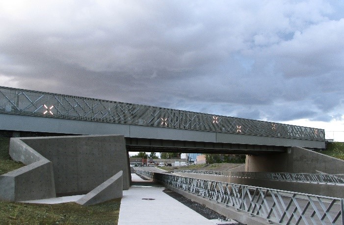
After the analysis, the structure that best met the criteria was a TPG (Through-Plate Girder Bridge) and deck which was chosen as the future railway viaduct.
As for the design consideration, given the large dead loads of 630 tons and the presence of two railway design vehicles (Cooper E90), which would generate approximately 1520 tons, with high main beams having a height of 3650 mm and stiffened by a system of horizontal and vertical stiffeners. Knee-brace internal stiffeners were incorporated at each main beam location to support the top of the beam to support the ballast platform.
The viaduct, approximately 27.76 m long and 10.0 m wide, supports two railway tracks installed on a ballasted steel floor (rails fixed on wooden sleepers embedded in the ballast) so that this section on the viaduct reproduces the same track conditions as on the adjacent embankments.
The weight of rails, sleepers and ballast and loads from railway vehicles are transmitted to the steel floor system connected to transverse beams (spacers) close to 700 mm, which in turn are supported by two main beams. For both ends of the viaduct, the arrangement of the spacers, their dimensions and their connections have been adapted to take into account the particular load distribution due to the angle.
The ballast lanes provide considerable protection for the viaduct’s steel floor system against damage from a potentially derailed car, as well as to the public traveling down the boulevard, from any ballast or other traffic-related material. railway or maintenance operations.
The firm of steel detailers Genifab, also participated in this project, they generated the 3D model of the steel structure with the details of the elements of the structure and they completed the drawings for the erection of the steel on the building site.
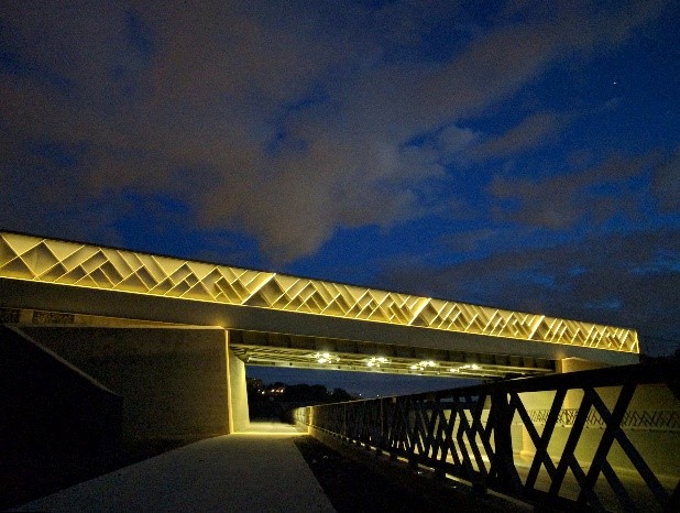
For maintenance and rail inspection purposes, two inspection bridges were added to the deck, one on each side. With the help and collaboration of the Architect, the designers replaced the guardrails of the walkways with two architectural balustrades. The viaduct is supported on two reinforced concrete abutments integrated into a set with the retaining walls and sidewalks along the boulevard.
SMi, the structural Engineers had partnered with Civiliti for the architectural and lighting component. This first collaboration with the Architects and designers of this Montreal firm has resulted in a resounding success for the new railway bridge by winning two awards at the 10th edition of the Grands Prix in Design. In designing a lighting system for both the railings and below the bridge, SMi engineers have attached paramount importance to both aspects of the lighting design, as well as to the safety elements.
The project, a real visual marvel, illustrates how simple utilitarian equipment can be transformed into an urban object that creates delight for passers-by. Focusing on the poetry and subtlety of lighting, the designers wanted to soften the disruptive effects of a site transformed in depth. The future Outremont site project of the University of Montréal goes well beyond the limits of university activity. It embraces urban collective life by providing a new living environment that will serve both the interests of the university community and those of the residents of the surrounding neighborhoods3.
REFERENCES:
(1): www.cisc-icca.ca
(2): Orthotropic Steel Deck Case Study: Hunt Club Pathway Connection to the Southeast Transitway Station Share: February 17, 2016. Published by: Marc Langlois CANAM
(3) Advantage Steel, Number 57, Summer Issue: An Essential Link-The design and construction of the Sir Ambrose Shea vertical lift bridge, by Hellen Christodoulou, Ph.D.ing., B.C.L., LL.B., M.B.A.,
CISC Quebec Region Manager