For practicality and economic reasons, codes are reluctant to enforce design for full elastic forces, especially where seismic forces are large. Inelastic design complicates the design substantially and has led to the concept of capacity-based design, a major departure from traditional design philosophy. The design becomes very challenging when seismic forces are significant, but wind or gravity load dictates some of the member sizes. This article briefly examines several common situations.
By Alfred Wong, P.Eng., F.CSCE
Capacity Design
Traditionally, building structures have been designed to resist seismic load in combination with gravity loads in accordance with the applicable load combinations in the building code. Since the introduction of capacity design requirements in CSA Standard S16, capacity-protected elements in seismic force-resisting systems (SFRS) other than conventional construction (CC) are generally designed to resist forces corresponding to the capacity of the yielding elements instead. Capacity design works well except when loads, other than seismic load, govern the design of the “yielding members” in the SFRS. In this case, the yielding members that are stronger than what are required to meet the seismic load combinations inflate the required resistance for the capacity protected elements, including the resistance of columns, connections, foundations and floor and roof diaphragms. Capacity design requirements do not apply to CC. For some applications, however, CC is either not permitted or unsuitable.

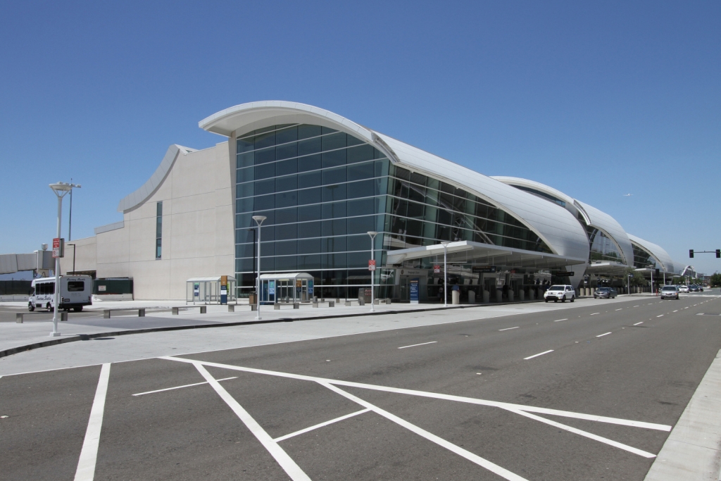
Figure 1: Minetta (San Jose) International Airport Terminal B Building – Courtesy of Magnusson Klemencic Assoc. Inc.
When Wind Effects Govern
Wind forces or effects, such as deformation and accelerations of taller buildings, may govern the member sizes of the SFRS, including the yielding elements. These situations include tall and mid-rise buildings subjected to moderate seismic hazard as well as tall buildings subjected to high seismic hazard. Moment resisting frames are generally more flexible as compared to braced frame and shear wall systems, hence they are more sensitive to wind related serviceability requirements.
When Gravity Effects Govern
Live load deflection or floor vibration control may govern the design of beams in moment resisting frames with long spans. Since the beams are the yielding members, use of beams stronger than what are required to resist seismic load inflates the columns, connection, panel zone, foundation and diaphragm forces.
Solutions & Options
S16 sets the upper bound for capacity design forces at forces corresponding to RdRo = 1.3 for members, horizontal diaphragms, foundations and ductile connections. Forces at this bound, however, are usually several times larger than the factored seismic forces in the yielding elements in a ductile system such as ductile moment-resisting frame (RdRo = 7.5). The upper bound forces may also be established using non-linear time-history analyses. Although the rules for non-linear time-history analyses are not well defined in S16-14, guidance is on the way.

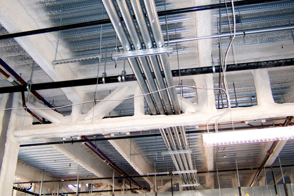
Figure 2: Special Truss Moment Frame – Minetta (San Jose) Int. Airport – Courtesy of Magnusson Klemencic Assoc. Inc.
Use of special systems, such as those incorporating seismic isolation or energy-dissipating devices, is also permitted. The burden to demonstrate that their performance meets or exceeds the safety level required in S16 and NBC rests with the structural engineer. S16 also permits the use of truss moment frames with ductile truss segments although S16-14 lacks specific requirement for the system. The trusses yield in shear near the mid span instead of flexural yielding near the columns, thereby separating the yielding mode from the flexural stiffness required for control of deformation due to wind or live load. Special truss moment frames have been used in the U.S., including prominent projects, such as the Terminal B Building and Concourse in Minetta (San Jose) International Airport (See Figures). Design provisions for special truss moment frames were introduced in AISC Specifications (now known as ANSI/AISC 341-16) in 1997 and research studies continued. Incorporation of the Canadian version is a logical development.
*This article was originally published in Advantage Steel no. 62 and can be found here.


