By C.P. (Ken) Rebel and Raj Singh
McElhanney Consulting Services Ltd.
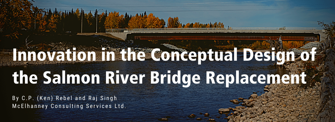
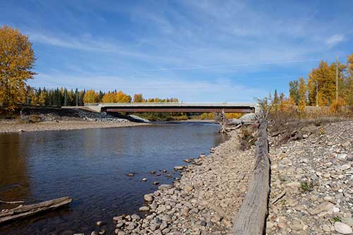
On a stretch of highway in northern British Columbia, 27km north of Prince George, a narrow two-lane truss bridge crossing the Salmon River had to be replaced due to its ageing structural condition and restricted functionality.
The 55-metre long single span structure had a small roadway width and a 5.4m roadway vertical clearance which was insufficient for the area’s truck traffic. The structure’s owner, the British Columbia Ministry of Transportation and Infrastructure (MoTI), engaged McElhanney to engineer the bridge replacement and includes highway engineering, traffic and environmental management, and electrical engineering services. McElhanney worked collaboratively with MoTI to prioritize project issues and stakeholder concerns to develop pertinent solutions. The options were evaluated using a Multi Account Evaluation (MAE) approach and a preferred design was recommended to the owner. We developed a new 67m long composite steel single span bridge, centred on the existing highway alignment, as the optimal solution which best addressed the project goals and design constraints. In addition to the two traffic lanes of the old bridge, the new bridge deck accommodates two 2m shoulders with a 1.8m-wide pedestrian sidewalk on one side, for a total deck width of 14m.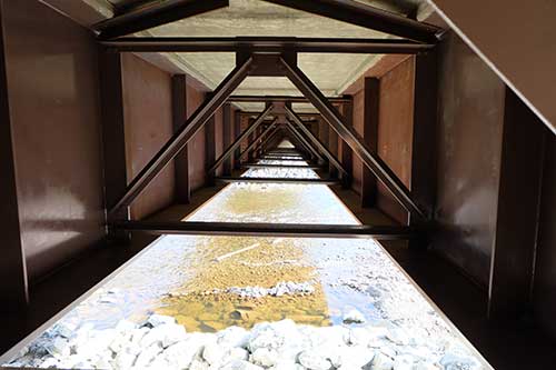
The Salmon River, a tributary of the Fraser River, is classified as a sensitive stream under the Fish Protection Act and is recognized as a vital habitat for fish and amphibian species. The optimal bridge solutions minimized impacts and disturbance to the habitat. Our first consideration during the conceptual design was selection of the highway alignment for the new bridge. We considered geometric improvements, influence on adjacent intersections, property acquisition, and environmental impacts. We identified three highway alignment options: upstream, downstream, or existing. The upstream alignment offered the advantage of improved sight lines for the Salmon Valley Road intersection. However, disadvantages included property acquisition and encroachment into the riparian area and floodplain of the Salmon River. Locating the highway alignment downstream required introduction of “s-curves” to the highway alignment and resulted in reduced sign distances for the existing accesses and intersections. We ultimately recommended the existing alignment, as it met the highway design criteria requirements, eliminated environmental disturbance, and did not require reconstruction and realignment of the adjacent intersections.
A hydrotechnical assessment of the site, completed by Northwest Hydraulics Consultants Ltd. of North Vancouver, analyzed the 100-year and 200-year open water peak flood levels and high ice elevations at the bridge, to define the waterway opening and to establish wildlife underpass evaluations. The recommended waterway for the new bridge featured a clear, trapezoidal channel with a bottom width of 48m, measured at low water level and end slopes at 2H: 1V resulting in a top width of 65.2m at the ice freeboard elevation. Except for in-stream piers, all other bridge components including the girders and abutments had to remain clear of this waterway opening. An initial high-level comparison indicated precast concrete girders were not economical for 50m plus span ranges (and are challenging to transport and erect, compared to steel girders). Furthermore, steel plate girders are common throughout British Columbia, and local fabricators and contractors are familiar with them, making the girders a cost-effective solution. Therefore, only steel girder options were considered in conceptual design.
We developed four bridge concepts:
1) a 67m single span with steel I girders
2) a 67m single span with steel box girders
3) a multi-span 15-50-15m with steel I-girders;
4) and a multi-span 15-50-15m with steel box girders.
 The options were compared using a MAE approach by scoring between one and five for each of the criteria, which included bridge, hydrotechnical, environmental, and geotechnical considerations. The 67m single span arrangement avoided significant encroachment into the waterway with only riprap protection required along the river banks to protect the abutments. The single span option also has less substructure costs due to the elimination of the river piers, and by minimizing the instream work the bridge could be constructed in less than a year. The plate girder option consistently scored highest on all accounts, except for aesthetic appeal, where it scored less than the box girder option. The final bridge has a cast-in-place, reinforced concrete deck and four steel plate girder lines. We put significant effort into reducing the depth of the steel plate girders, through a detailed analysis of flexural frequency of the structure, dead and live loads, and deflections. Shallowing up the girders enabled a reduction in the height and length of the roadway approach fills on the project.” The final design resulted in shallow 2.1m deep girders with a slenderness ratio of about 32.
The client completed a bore hole investigation in the winter of 2015, 30m south of the south abutment, and 30m north of the north abutment. Underlying sand, gravel, and an extensive thick layer of stiff-to-hard, low-to-intermediate plastic silty clay with sporadic boulders was observed, and steel pipe piles were chosen for the piled foundations. The bridge abutments were designed to resist horizontal forces from retaining soil pressures on the backwalls, in addition to vertical loads from the design dead and live loads. To efficiently carry the abutment demands, we designed the abutment with two rows of piles that transfer a substantial portion of the moment induced into axial compression in the front row (river side) of piles and axial tension into the rear row (abutment soils side) of piles. Two rows of 762mm diameter steel piles with four piles per row spaced at three pile diameters, with the front row pile length at 28m and the rear pile length at 18m was the optimum arrangement of piles to satisfy all loading requirements.
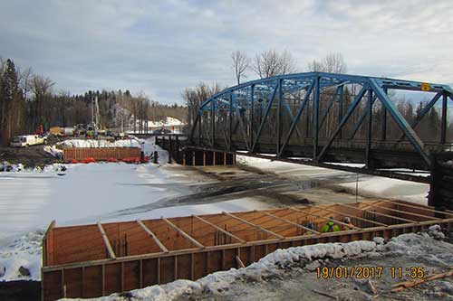
 Two-way traffic flow needed to be maintained for the duration of the bridge’s construction. Therefore, a two-lane detour was needed until such a time that traffic flow could be moved to the new highway. Constructing the detour on the downstream side of the bridge was the recommended option, as it required a shorter bridge span, with available right-of-way on the north side, and an existing pullout area on the southeast side of the bridge. We evaluated three options for the temporary detour bridge: sliding the existing truss bridge transversely to the downstream detour alignment, constructing the new superstructure offline on temporary foundations supports and sliding it into final position alignment, or utilizing a temporary Acrow bridge on the downstream detour alignment. Using the existing truss bridge as the detour bridge was the most cost-effective solution, with minimal throw away costs. The existing steel truss bridge was transversely relocated 15m downstream along the detour alignment during a four-hour night closure of the highway, clearing the space to allow the construction of the new bridge along the existing alignment.
Structural steel offered the most effective, constructible and sustainable solution for the key superstructure and foundation components for this bridge, resulting in a project successfully completed on schedule and within the owner’s approved budget.