
QUESTION: (SUMMER2016) I am proportioning a mono-symmetric I-girder whose web-slenderness, h/w, marginally satisfies the Class 3 limit for W-shapes in pure bending in accordance with Table 2 of S16-09. Does this limit apply to mono-symmetric sections?
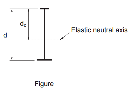
ANSWER: No, the limits for I-sections are provided in Table 2 of S16-09 for sections with equal flanges. CSA Standard S6, Canadian Highway Bridge Design Code, in Clause 10.10.3.1, addresses Class 3 web-limits for mono-symmetric I-sections. In this clause, the value of h is replaced by 2dc, where dc is the distance from the neutral axis to the compressive extreme fibre (see Figure).
QUESTION: (2015) When using the direct method in accordance with Clause 9.2.6.2 of CSA S16-14, I was surprised to find that, for a given column force, Cf, the bracing force, Pb, increases as the number of braces is increased from 1 to 2. Does this make sense?
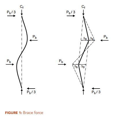
ANSWER: Intuitively, it would seem that adding braces to stabilize a compression member should reduce the brace force per brace, as there are more braces to “share” the stabilizing forces. But in fact, the opposite is true. It should be noted that the brace forces in two adjacent braces do not act in the same direction but the opposite is true (Figure 1). Given a column force, Cf, and in compliance with a maximum permitted out-of-plumbness, ∆0/L, the bracing force, Pb, is directly proportional to the factor β, which takes on values of 2 and 3 for 1 and 2 equally spaced braces respectively. In this case, the brace force, Pb, increases by 50%.
QUESTION: (SUMMER2014) I am designing a building structure consisting of a simple gravity frame and a perimeter rigid frame, which serves as the lateral-force resisting system. There is no braced bay or shear wall. Several gravity columns are subjected to significant bending about the strong axis due to a large connection eccentricity. Should these wide-flange columns be designed as beam-columns of an unbraced frame? How are the values for U1x determined?
ANSWER: No, this is a braced-frame situation. Despite the absence of braced bent, the gravity columns are ‘leaners’, i.e. they do not participate as primary lateral-force resisting members. The U1x values can be calculated in accordance with Clause 13.8.4 of CSA S16 but the U1x values for determination of cross-sectional strength and lateral-torsional buckling strength must not be less than 1.0.
QUESTION: (SPRING2014) I heard about the notional load requirement in the design of building structures but I cannot locate the notional load provision in the building code. Where do I find them?
ANSWER: You will find the provision for notional loads in CSA Standard S16-09, Design of Steel Structures. The Standard permits the second order effects due to gravity loads acting on the displaced structure under horizontal loads to be accounted for by using a P-delta analysis. In addition, the effects due to out-of-plumbness and partial yielding may be approximated by a set of horizontal loads, which are referred to as notional loads. The notional load to be applied at each level in addition to any other horizontal load is taken as 0.5 per cent of the concurrent gravity load acting on that level. Alternatively, a rigorous second-order analysis that accounts for both geometric nonlinearity, including out-of-plumbness, and partial yielding may be used.
QUESTION: (FALL2013) When checking flexural buckling of a channel section under axial load, what radius of gyration should be used to calculate Fex and Fey?
ANSWER: In S16-09 Clause 13.3.2, the elastic buckling stresses are given by:
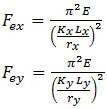
For singly-symmetric sections such as channels, the same clause specifies that the y-axis is taken as the axis of symmetry. But when using the tables of properties and dimensions for channels in Part 6 of the Handbook of Steel Construction, the x-axis is defined as the axis of symmetry. Therefore, Fex should be calculated using the radius of gyration ry as given in the Handbook tables, and likewise Fey should be calculated using rx.
QUESTION: (FALL2012) How do I determine the elastic bending resistance of a cantilever plate subject to lateral-torsional buckling?
ANSWER: For a fix-ended plate subject to bending about its strong axis but laterally unbraced, the Guide to Stability Design Criteria for Metal Structures, 6th Edition (R.D. Ziemian, John Wiley & Sons, 2010) gives expressions for the elastic buckling moment (Mu), depending on the height of load application. For example, when subjected to a point load at its tip (see Figure):
a) For top surface loading: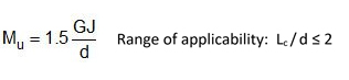 b) For shear centre loading:
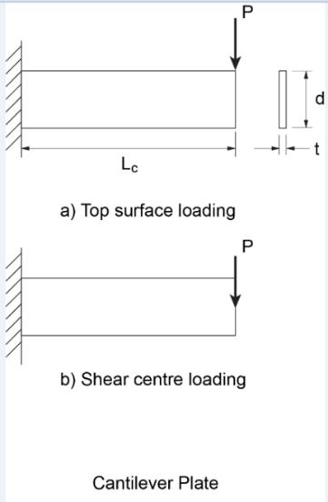
NOTE: In Advantage Steel #44, this column referenced the expressions for the elastic lateral-torsional buckling moment of cantilevers provided in the Guide to Stability Design Criteria for Metal Structures, 6th Edition. In comparison with recent studies using finite element analyses, the expression “Mc = 1.5GJ/d” gives unconservative values for plates (rectangular section) and long cantilevers of I-sections prone to lateral-torsional buckling. It should not be used for plate cantilevers significantly longer than twice their depth.
QUESTION: (SUMMER2012) In the design of continuous beams and Gerber beams can I assume the inflection points are laterally braced against lateral-torsional buckling?
ANSWER: One must not confuse the inflection points in the vertical bending moment diagram with the inflection points in the laterally buckled shape. In general, the buckled shape is not known at the design stage. Since the inflection points in the bending moment diagram generally do not coincide with those of the buckled shape they should not be taken as laterally braced unless they are braced.

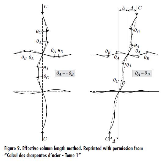
QUESTION: (SUMMER2012) I have used the effective-length method to design columns in sway-permitted frames as well as those in sway-prevented frames. But I cannot find the effective-length nomograph for sway-permitted frames in CSA Standard S16. Is the effective-length method still valid?
ANSWER:
The effective column length method attempts to approximate the elastic critical column load for a regular frame that is without primary moments and consists of identical beams in each level and identical columns (see Figure 2). This idealized frame model does not account for any second-order effects in the beams at all. Moreover, in comparison with modern analysis methods that account for second-order effects etc., it usually fails to provide accurate results for real frames. Since the introduction of S16.1-M89, the Standard has abandoned the effective length design method for sway-permitted frames. Accordingly, the nomograph for sway-permitted frames has since been excluded.
When an elastic analysis is used, the current standard, S16-09, requires the application of a second-order analysis that directly accounts for sway effects. Alternatively, P-delta effects are included using the amplification factor, U2. In addition, notional loads are applied to account for the effects of partial yielding and initial out-of-plumbness.
Note: When P-delta effects and notional loads are accounted for, the use of an effective column length for sway-prevented case (K ≤ 1) is permitted for consideration of lateral-torsional buckling. However, it is assumed in the effective length method that all members remain elastic prior to buckling. Hence the strong-column-weak-beam requirements for non-conventional construction, where applicable, may render its use inappropriate.
QUESTION: (SPRING2012) When I use the amplifier, U2, to account for P-Δ effects in accordance with S16, should I apply U2 to amplify the notional loads as well?
ANSWER: Yes, notional loads should also be amplified when U2 is used to account for P-Δ effects.
QUESTION: Part A: (FALL2011) How do I calculate the axial compressive resistance of a member subject to elastic local buckling?
ANSWER: Two methods are provided in CSA Standard S16-09, the effective area method and the effective yield stress method.
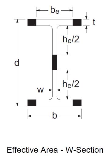
Effective area methodEngineers are generally familiar with the concept of effective area when designing columns subject to elastic local buckling. Such sections are expected to undergo local buckling before reaching the yield load in axial compression, AFy. They are designed in accordance with CSA S16-09 Clause 13.3.5 (a) whenever the width-to-thickness ratio of the flanges or web exceeds the limits given in Table 1 of S16-09. When calculating the axial compressive resistance, a portion or portions of the cross-section is considered ineffective and is therefore omitted. Considering a wide-flange section, for example, the effective cross-sectional area, Ae, is computed as follows: If the flanges exceed the maximum width-to-thickness ratio of Table 1, the area of the tips (shaded parts in the figure shown) is removed, such that the remaining effective flange width, be, meets the maximum ratio; similarly, the effective web depth is taken as he as shown in the figure. The effective portions of the flanges and web together make up the effective area, Ae.
Effective yield stress method
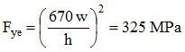
Perhaps less familiar is the effective yield stress method, which S16-09 also permits for calculating the axial compressive resistance. According to this concept first introduced in S16-01, the cross-sectional area remains intact, but the yield stress is reduced to account for local buckling. The effective yield stress, Fye, is taken as the reduced yield stress determined from the width-to-thickness ratio meeting the limit in Table 1. If both the flanges and the web are subject to elastic local buckling, two separate effective yield stresses are calculated. For simplicity, the member resistance is based on the lower of the two values.
QUESTION: Part B: (FALL2011) Do the methods provided in CSA S16-09 give the same answer?
ANSWER:
ANSWER: No, the effective area method and the effective yield stress method, in general, do not give the same answer. An example is presented below to illustrate both methods. Consider a laterally supported W360x72 column (L = 0) made of ASTM A992 steel. The cross-sectional area is A = 9100 mm2 and the specified yield stress, Fy, = 345 MPa. The factored axial compressive resistance will be determined on the basis of (1) effective area and (2) effective yield stress.
(1) Effective area methodCheck the width-to-thickness ratios of the flanges and web:
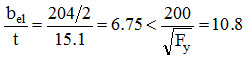 The flanges are not subject to local buckling.
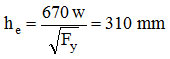
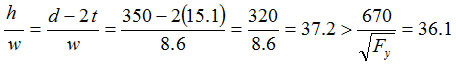 The web is subject to elastic local buckling. The effective web depth is given by:
 The effective area is:
 And the compressive resistance is:
QUESTION: Part C: (FALL2011) Which method is used to calculate the values for sections subject to elastic local buckling in the Column Tables and Angle Strut Tables in the CISC Handbook?
ANSWER: Both methods are used to calculate the factored compressive resistances, Cr, for W-columns subject to elastic local buckling and the tabulated values are the larger of the two. Only the effective area method is used to calculate the Cr values for other columns and struts. Angle sections that exceed the maximum b-to-t limit in Table 1 are excluded from the star-shaped angle strut tables.